-
VK/D3D12_Visibility Buffer架构流程实现
之前介绍过UE_Visibility Buffer & Deferred Material,现在我们来看一下Visibility Buffer渲染架构的具体实现流程,本文主要参考使用图形大牛Wolfgang Engel的The filtered and culled Visibility Buffer技术介绍及代码来分析Visibility Buffer的主要架构与实现流程。
一、G-Buffer与Visibility Buffer
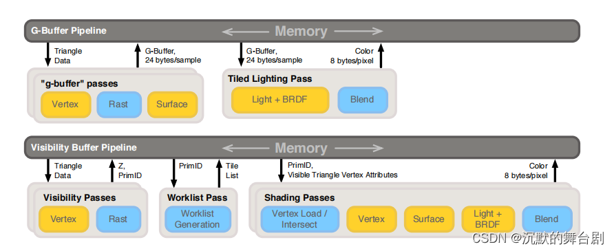
此处仅放一张管线图,具体优劣介绍见之前文章:UE_Visibility Buffer & Deferred Material。
此处大概介绍一下代码主要实现流程中包括以下两步:- 使用常规绘制填充Visibility Buffer;
- 使用Visibility Buffer进行着色数据获取进行Shading;
当然了,其中还有好多过程性的渲染优化,此处就不展开了。
二、Visibility Buffer架构实现流程
2.1 Visibility Buffer格式说明
首先我们来看一下承载Visibility Buffer需要的格式:每个三角形的Visibility Buffer使用的RenderTarget是RGBA8格式的纹理,其中存储了如下的一些信息:
-
1bit的Alpha-Masked信息: 用于指明当前面片是否alpha masking(alpha test)
-
8bit的drawID: 对应的是indirect draw call的id,这个id可以表明当前的面片属于哪个draw call,8bit就对应最多256个draw call
-
23bit的triangleID,: 这个表示的是当前面片在当前draw call中的偏移,是每个draw call中的局部ID
这个RT在调用ExecuteIndirect的时候完成填充,同时还会完成Depth Buffer的输出,每个ExecuteIndirect指令调用都会读取VB/IB以及Material Buffer(简称MB)
2.2 填充Visibility Buffer
首先说一下此处管线的mesh的数据只需要位置信息即可,其余的都可以通过绘制传进去。
我们来看一下顶点着色器的主要流程:#ifdef VULKAN #extension GL_ARB_shader_draw_parameters : enable #endif STRUCT(VsInOpaque) { DATA(float3, position, POSITION); }; STRUCT(PsInOpaque) { DATA(float4, position, SV_Position); #if defined(VULKAN) || defined(ORBIS) || defined(PROSPERO) || defined(METAL) DATA(FLAT(uint), drawId, TEXCOORD3); #endif }; PsInOpaque VS_MAIN( VsInOpaque In, SV_InstanceID(uint) instanceId ) { INIT_MAIN; PsInOpaque Out; Out.position = mul(Get(transform)[VIEW_CAMERA].mvp, float4(In.position.xyz, 1.0f)); #ifdef VULKAN Out.drawId = gl_DrawIDARB; #elif defined(ORBIS) || defined(PROSPERO) || defined(METAL) Out.drawId = instanceId; #endif RETURN(Out); }- 1
- 2
- 3
- 4
- 5
- 6
- 7
- 8
- 9
- 10
- 11
- 12
- 13
- 14
- 15
- 16
- 17
- 18
- 19
- 20
- 21
- 22
- 23
- 24
- 25
- 26
- 27
- 28
- 29
- 30
片元着色器主要实现流程如下:
STRUCT(PsInOpaque) { DATA(float4, position, SV_Position); #if defined(VULKAN) || defined(ORBIS) || defined(PROSPERO) || defined(METAL) DATA(FLAT(uint), drawId, TEXCOORD3); #endif }; float4 unpackUnorm4x8(uint p) { return float4(float(p & 0x000000FF) / 255.0, float((p & 0x0000FF00) >> 8) / 255.0, float((p & 0x00FF0000) >> 16) / 255.0, float((p & 0xFF000000) >> 24) / 255.0); } uint calculateOutputVBID(uint drawID, uint primitiveID) { return ((drawID << DRAW_ID_LOW_BIT) & DRAW_ID_MASK) | ((primitiveID << PRIM_ID_LOW_BIT) & PRIM_ID_MASK); } float4 PS_MAIN( PsInOpaque In, SV_PrimitiveID(uint) primitiveId ) { INIT_MAIN; float4 Out; Out = unpackUnorm4x8(calculateOutputVBID(getDrawID(), primitiveId)); RETURN(Out); }- 1
- 2
- 3
- 4
- 5
- 6
- 7
- 8
- 9
- 10
- 11
- 12
- 13
- 14
- 15
- 16
- 17
- 18
- 19
- 20
- 21
- 22
- 23
- 24
- 25
- 26
- 27
- 28
- 29
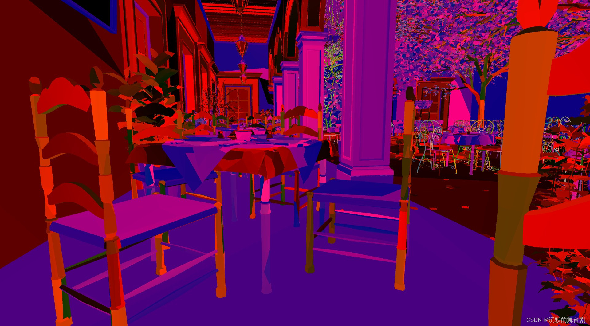
其中主要使用位置信息来记录Alpha-Masked、drawID、triangleID的数据,先将其压缩为uint,再转为float4输出到RGBA8缓冲区中。
经过填充后,可以获得以下数据:
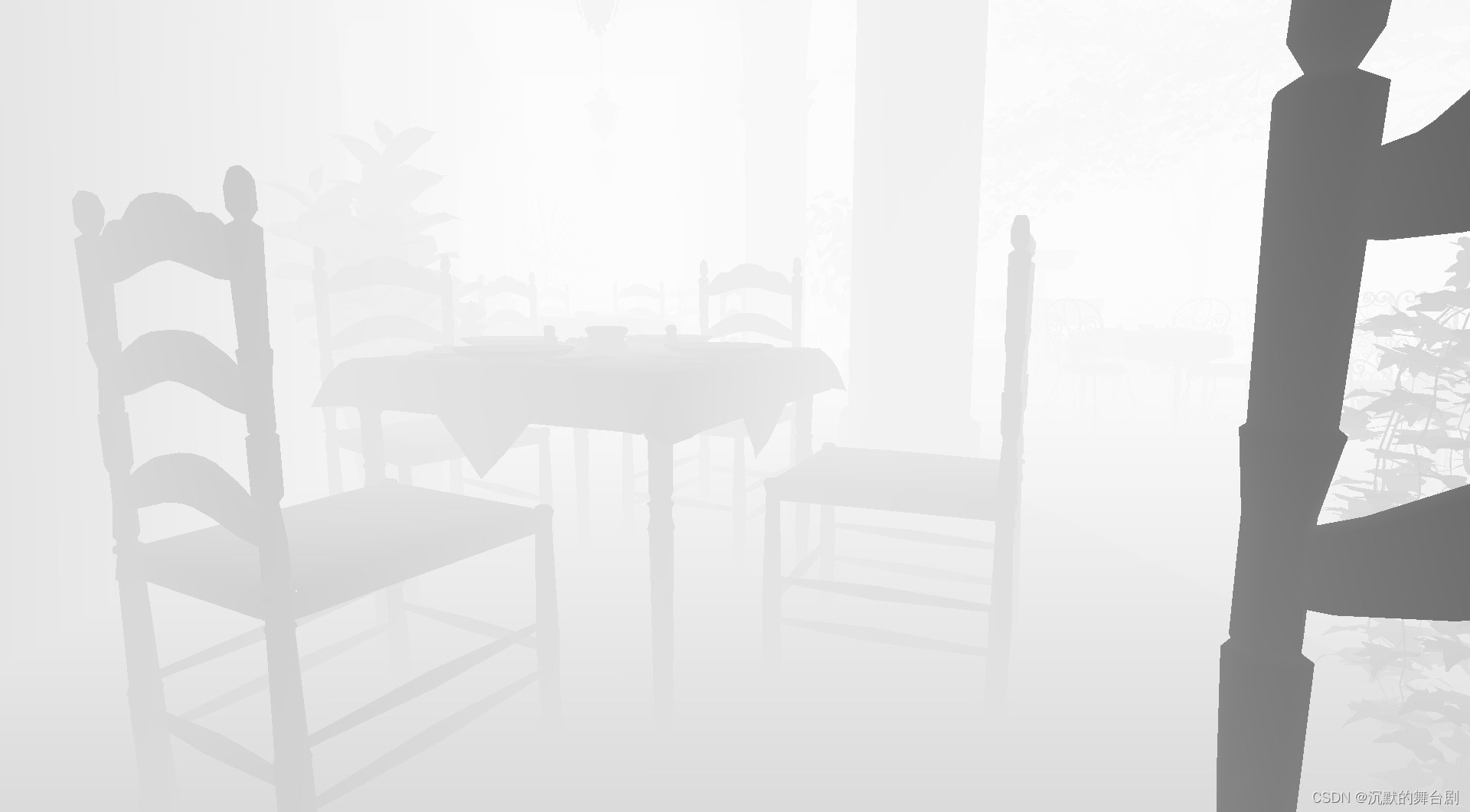
同时还会生成一个深度图:
2.3 计算Shading
Visibility Buffer跟Depth Buffer填充完成之后,就可以考虑进行Shading操作了。不过在此之前,我们首先来看一下除了上边生成的像素级可见数据外,我们还需要哪些数据:
- Vertex Buffer: 中的数据布局包含:Position,Texture coordinates,Normals,Tangents。(当然了其他变种做法也可以把重心用16 bits表示放 R32G32_UINT 纹理中);
- **Index Buffer:**存储对应的索引数据,在shading中进行对应的查找索引用到;
- Material Buffer: shading用到的最后一项数据为texture id或者material buffer,这个数据对应的是场景中的大量material数据。
总的来说就是:在光照着色阶段,只需要根据InstanceID和PrimitiveID从全局的Vertex Buffer中索引到相关三角形的信息;进一步地,根据像该素的重心坐标,对Vertex Buffer内的顶点信息(UV,Tangent Space等)进行插值得到逐像素信息;再进一步地,根据MaterialID去索引相关的材质信息,执行贴图采样等操作,并输入到光照计算环节最终完成着色,有时这类方法也被称为Deferred Texturing。
下边我们来看一下具体的实现:
顶点着色器如下(简单三角形绘制):
// 加载每个像素的绘制/三角形Id并重建插值的顶点数据。 STRUCT(VSOutput) { DATA(float4, position, SV_Position); DATA(float2, screenPos, TEXCOORD0); #line 30 }; // Vertex shader VSOutput VS_MAIN( uint vertexId : SV_VERTEXID ) { //生成一个全屏三角形使用当前的vertexId来自动计算顶点划分。 这种方法避免使用顶点/索引缓冲区来生成一个全屏四边形。 //INIT_MAIN; VSOutput result; result.position.x = (vertexId == 2 ? 3.0 : -1.0); result.position.y = (vertexId == 0 ? -3.0 : 1.0); result.position.zw = float2(0, 1); result.screenPos = result.position.xy; return (result); }- 1
- 2
- 3
- 4
- 5
- 6
- 7
- 8
- 9
- 10
- 11
- 12
- 13
- 14
- 15
- 16
- 17
- 18
- 19
- 20
接下来重点来了,最重要的片元着色器如下:
STRUCT(VSOutput) { DATA(float4, position, SV_Position); DATA(float2, screenPos, TEXCOORD0); }; struct DerivativesOutput { float3 db_dx; float3 db_dy; }; struct TransparentNodeOIT { uint triangleData; uint next; }; struct NodeFinalOIT { float3 color; float depth; uint next; }; // 从投影的屏幕空间顶点计算三角形的偏导数 DerivativesOutput computePartialDerivatives(float2 v[3]) { DerivativesOutput result; float d = 1.0 / determinant(f2x2(v[2] - v[1], v[0] - v[1])); result.db_dx = float3(v[1].y - v[2].y, v[2].y - v[0].y, v[0].y - v[1].y) * d; result.db_dy = float3(v[2].x - v[1].x, v[0].x - v[2].x, v[1].x - v[0].x) * d; return result; } // 使用偏导数在点d插入顶点属性的辅助函数 float3 interpolateAttribute(float3x3 attributes, float3 db_dx, float3 db_dy, float2 d) { float3 attribute_x = mul(db_dx, attributes); float3 attribute_y = mul(db_dy, attributes); float3 attribute_s = getRow0(attributes); return (attribute_s + d.x * attribute_x + d.y * attribute_y); } float interpolateAttribute(float3 attributes, float3 db_dx, float3 db_dy, float2 d) { float attribute_x = dot(attributes, db_dx); float attribute_y = dot(attributes, db_dy); float attribute_s = attributes[0]; return (attribute_s + d.x * attribute_x + d.y * attribute_y); } struct GradientInterpolationResults { float2 interp; float2 dx; float2 dy; }; // 使用偏导数插值2D属性,生成纹理采样的dx和dy。 GradientInterpolationResults interpolateAttributeWithGradient(f3x2 attributes, float3 db_dx, float3 db_dy, float2 d, float2 pTwoOverRes) { float3 attr0 = getRow0(attributes); float3 attr1 = getRow1(attributes); float2 attribute_x = float2(dot(db_dx, attr0), dot(db_dx, attr1)); float2 attribute_y = float2(dot(db_dy, attr0), dot(db_dy, attr1)); float2 attribute_s = getCol0(attributes); GradientInterpolationResults result; result.dx = attribute_x * pTwoOverRes.x; result.dy = attribute_y * pTwoOverRes.y; result.interp = (attribute_s + d.x * attribute_x + d.y * attribute_y); return result; } float depthLinearization(float depth, float near, float far) { return (2.0 * near) / (far + near - depth * (far - near)); } // Static descriptors #if(SAMPLE_COUNT > 1) RES(Tex2DMS(float4, SAMPLE_COUNT), vbTex, UPDATE_FREQ_NONE, t0, binding = 14); #else RES(Tex2D(float4), vbTex, UPDATE_FREQ_NONE, t0, binding = 14); #endif RES(Buffer(uint), headIndexBufferSRV, UPDATE_FREQ_NONE, t30, binding = 15); RES(Buffer(TransparentNodeOIT), vbDepthLinkedListSRV, UPDATE_FREQ_NONE, t31, binding = 16); RES(Tex2D(float), shadowMap, UPDATE_FREQ_NONE, t101, binding = 18); #if defined(METAL) || defined(ORBIS) || defined(PROSPERO) RES(Tex2D(float4), diffuseMaps[MATERIAL_BUFFER_SIZE], UPDATE_FREQ_NONE, t0, binding = 19); RES(Tex2D(float4), normalMaps[MATERIAL_BUFFER_SIZE], UPDATE_FREQ_NONE, t1, binding = 19 + MAX_TEXTURE_UNITS); RES(Tex2D(float4), specularMaps[MATERIAL_BUFFER_SIZE], UPDATE_FREQ_NONE, t2, binding = 19 + MAX_TEXTURE_UNITS * 2); #else RES(Tex2D(float4), diffuseMaps[MATERIAL_BUFFER_SIZE], space4, t0, binding = 19); RES(Tex2D(float4), normalMaps[MATERIAL_BUFFER_SIZE], space5, t0, binding = 19 + MAX_TEXTURE_UNITS); RES(Tex2D(float4), specularMaps[MATERIAL_BUFFER_SIZE], space6, t0, binding = 19 + MAX_TEXTURE_UNITS * 2); #endif RES(ByteBuffer, vertexPos, UPDATE_FREQ_NONE, t10, binding=0); RES(ByteBuffer, vertexTexCoord, UPDATE_FREQ_NONE, t11, binding=1); RES(ByteBuffer, vertexNormal, UPDATE_FREQ_NONE, t12, binding=2); RES(ByteBuffer, vertexTangent, UPDATE_FREQ_NONE, t13, binding=3); RES(ByteBuffer, filteredIndexBuffer, UPDATE_FREQ_PER_FRAME, t14, binding=4); RES(Buffer(uint), indirectMaterialBuffer, UPDATE_FREQ_PER_FRAME, t15, binding=5); RES(Buffer(uint), indirectDrawArgs[3], UPDATE_FREQ_PER_FRAME, t17, binding=9); RES(Buffer(MeshConstants), meshConstantsBuffer, UPDATE_FREQ_NONE, t16, binding=6); RES(Buffer(LightData), lights, UPDATE_FREQ_NONE, t19, binding=11); RES(ByteBuffer, lightClustersCount, UPDATE_FREQ_PER_FRAME, t20, binding=12); RES(ByteBuffer, lightClusters, UPDATE_FREQ_PER_FRAME, t21, binding=13); RES(SamplerState, textureSampler, UPDATE_FREQ_NONE, s0, binding = 7); RES(SamplerState, depthSampler, UPDATE_FREQ_NONE, s1, binding = 8); //数据转换并进行着色 float4 tri_data_to_frag_color(float4 inPosition, float2 screenPos, uint drawID, uint triangleID, uint trans1_opaque0, uint alpha1_opaque0) { // TODO: Inefficient uint materialIndex = GEOMSET_OPAQUE; materialIndex = materialIndex; if (alpha1_opaque0 == 1) materialIndex = GEOMSET_ALPHATESTED; if (trans1_opaque0 == 1) materialIndex = GEOMSET_TRANSPARENT; // 这是当前绘制批处理的起始顶点 uint startIndexOffset = INDIRECT_DRAW_ARGUMENTS_STRUCT_OFFSET + 2; //uint startIndex = alpha1_opaque0 == 0 ? // Get(indirectDrawArgs)[0][drawID * INDIRECT_DRAW_ARGUMENTS_STRUCT_NUM_ELEMENTS + startIndexOffset] : // Get(indirectDrawArgs)[1][drawID * INDIRECT_DRAW_ARGUMENTS_STRUCT_NUM_ELEMENTS + startIndexOffset]; uint startIndex = Get(indirectDrawArgs)[GEOMSET_OPAQUE][drawID * INDIRECT_DRAW_ARGUMENTS_STRUCT_NUM_ELEMENTS + startIndexOffset]; if (alpha1_opaque0 == 1) startIndex = Get(indirectDrawArgs)[GEOMSET_ALPHATESTED][drawID * INDIRECT_DRAW_ARGUMENTS_STRUCT_NUM_ELEMENTS + startIndexOffset]; if (trans1_opaque0 == 1) startIndex = Get(indirectDrawArgs)[GEOMSET_TRANSPARENT][drawID * INDIRECT_DRAW_ARGUMENTS_STRUCT_NUM_ELEMENTS + startIndexOffset]; uint triIdx0 = (triangleID * 3 + 0) + startIndex; uint triIdx1 = (triangleID * 3 + 1) + startIndex; uint triIdx2 = (triangleID * 3 + 2) + startIndex; uint index0 = LoadByte(Get(filteredIndexBuffer), triIdx0 << 2); uint index1 = LoadByte(Get(filteredIndexBuffer), triIdx1 << 2); uint index2 = LoadByte(Get(filteredIndexBuffer), triIdx2 << 2); // 加载3个顶点的顶点数据 float3 v0pos = asfloat(LoadByte4(Get(vertexPos), index0 * 12)).xyz; float3 v1pos = asfloat(LoadByte4(Get(vertexPos), index1 * 12)).xyz; float3 v2pos = asfloat(LoadByte4(Get(vertexPos), index2 * 12)).xyz; // 转换位置到裁剪空间 float4 pos0 = mul(Get(transform)[VIEW_CAMERA].mvp, float4(v0pos, 1.0f)); float4 pos1 = mul(Get(transform)[VIEW_CAMERA].mvp, float4(v1pos, 1.0f)); float4 pos2 = mul(Get(transform)[VIEW_CAMERA].mvp, float4(v2pos, 1.0f)); // 计算齐次坐标w的倒数,因为它会被用到很多次 float3 one_over_w = 1.0f / float3(pos0.w, pos1.w, pos2.w); // 投影顶点位置来计算2D透视后的位置 pos0 *= one_over_w[0]; pos1 *= one_over_w[1]; pos2 *= one_over_w[2]; float2 pos_scr[3] = { pos0.xy, pos1.xy, pos2.xy }; // 计算偏导数。 这对于插值每个像素的三角形属性是必要的。 DerivativesOutput derivativesOut = computePartialDerivatives(pos_scr); // 计算从投影顶点0指向当前屏幕点的增量向量(d) float2 d = screenPos + -pos_scr[0]; //为三角形的三个顶点插入1/w (one_over_w),使用重心坐标和delta向量 float w = 1.0f / interpolateAttribute(one_over_w, derivativesOut.db_dx, derivativesOut.db_dy, d); //在这个屏幕点重构Z值,只执行必要的矩阵*向量乘法操作,涉及到计算Z float z = w * getElem(Get(transform)[VIEW_CAMERA].projection, 2, 2) + getElem(Get(transform)[VIEW_CAMERA].projection, 3, 2); //计算世界位置坐标: //首先,在这一点的投影坐标计算使用screenPos和计算的Z值在这一点。 //然后,将透视投影坐标乘以逆视图投影矩阵(invVP)得到世界坐标 float3 position = mul(Get(transform)[VIEW_CAMERA].invVP, float4(screenPos * w, z, w)).xyz; //纹理坐标插值,对纹理坐标应用透视校正 f3x2 texCoords = make_f3x2_cols( unpack2Floats(LoadByte(Get(vertexTexCoord), index0 << 2)) * one_over_w[0], unpack2Floats(LoadByte(Get(vertexTexCoord), index1 << 2)) * one_over_w[1], unpack2Floats(LoadByte(Get(vertexTexCoord), index2 << 2)) * one_over_w[2] ); // 插值纹理坐标和计算纹理采样的梯度与mipmapping支持 GradientInterpolationResults results = interpolateAttributeWithGradient(texCoords, derivativesOut.db_dx, derivativesOut.db_dy, d, Get(twoOverRes)); float linearZ = depthLinearization(z/w, Get(CameraPlane).x, Get(CameraPlane).y); float mip = pow(pow(linearZ, 0.9f) * 5.0f, 1.5f); float2 texCoordDX = results.dx * w * mip; float2 texCoordDY = results.dy * w * mip; float2 texCoord = results.interp * w; /LOAD/// // 切线插值 // 对切线应用透视分割 float3x3 tangents = make_f3x3_rows( decodeDir(unpackUnorm2x16(LoadByte(Get(vertexTangent), index0 << 2))) * one_over_w[0], decodeDir(unpackUnorm2x16(LoadByte(Get(vertexTangent), index1 << 2))) * one_over_w[1], decodeDir(unpackUnorm2x16(LoadByte(Get(vertexTangent), index2 << 2))) * one_over_w[2] ); float3 tangent = normalize(interpolateAttribute(tangents, derivativesOut.db_dx, derivativesOut.db_dy, d)); // BaseMaterialBuffer返回常量偏移值 // 下面的值定义了一次绘制的间接绘制调用的最大数量。 这个值取决于场景中的子网格或单个对象的数量。 改变场景需要相应地改变这个值。 // #define MAX_DRAWS_INDIRECT 300 // // 这些值是用来指向材料数据的偏移量,这取决于几何形状的类型和剔除视图 // #define MATERIAL_BASE_ALPHA0 0 // #define MATERIAL_BASE_NOALPHA0 MAX_DRAWS_INDIRECT // #define MATERIAL_BASE_ALPHA1 (MAX_DRAWS_INDIRECT*2) // #define MATERIAL_BASE_NOALPHA1 (MAX_DRAWS_INDIRECT*3) uint materialBaseSlot = BaseMaterialBuffer(materialIndex, VIEW_CAMERA); // materialBaseSlot + drawID 可能的结果如下 // 0 - 299 - shadow alpha // 300 - 599 - shadow no alpha // 600 - 899 - camera alpha uint materialID = Get(indirectMaterialBuffer)[materialBaseSlot + drawID]; // 使用插值属性计算像素颜色 // 从X和Y重建法线贴图Z // 从数组中获取纹理。 float4 normalMapRG; float4 diffuseColor; float4 specularColor; BeginNonUniformResourceIndex(materialID, MAX_TEXTURE_UNITS); normalMapRG = SampleGradTex2D(Get(normalMaps)[materialID], Get(textureSampler), texCoord, texCoordDX, texCoordDY); diffuseColor = SampleGradTex2D(Get(diffuseMaps)[materialID], Get(textureSampler), texCoord, texCoordDX, texCoordDY); specularColor = SampleGradTex2D(Get(specularMaps)[materialID], Get(textureSampler), texCoord, texCoordDX, texCoordDY); EndNonUniformResourceIndex(); float3 reconstructedNormalMap; reconstructedNormalMap.xy = normalMapRG.ga * 2.0f - 1.0f; reconstructedNormalMap.z = sqrt(1 - dot(reconstructedNormalMap.xy, reconstructedNormalMap.xy)); //正常插值 //对法线应用透视除法 float3x3 normals = make_f3x3_rows( decodeDir(unpackUnorm2x16(LoadByte(Get(vertexNormal), index0 << 2))) * one_over_w[0], decodeDir(unpackUnorm2x16(LoadByte(Get(vertexNormal), index1 << 2))) * one_over_w[1], decodeDir(unpackUnorm2x16(LoadByte(Get(vertexNormal), index2 << 2))) * one_over_w[2] ); float3 normal = normalize(interpolateAttribute(normals, derivativesOut.db_dx, derivativesOut.db_dy, d)); // 从法线和切线计算顶点副法线 float3 binormal = normalize(cross(tangent, normal)); // 使用法线映射和切空间向量计算像素法线 normal = reconstructedNormalMap.x * tangent + reconstructedNormalMap.y * binormal + reconstructedNormalMap.z * normal; // 漫射颜色 float4 posLS = mul(Get(transform)[VIEW_SHADOW].vp, float4(position, 1.0f)); float Roughness = clamp(specularColor.a, 0.05f, 0.99f); float Metallic = specularColor.b; float ao = 1.0f; bool isTwoSided = (alpha1_opaque0 == 1 || trans1_opaque0 == 1) && bool(Get(meshConstantsBuffer)[materialID].twoSided); bool isBackFace = false; float3 ViewVec = normalize(Get(camPos).xyz - position.xyz); //如果它是背面,这应该是< 0,但我们的网格的边缘法线是平滑的y if (isTwoSided && dot(normal, ViewVec) < 0.0f) { //法线反转 normal = -normal; isBackFace = true; } float3 HalfVec = normalize(ViewVec - Get(lightDir).xyz); float3 ReflectVec = reflect(-ViewVec, normal); float NoV = saturate(dot(normal, ViewVec)); float NoL = dot(normal, -Get(lightDir).xyz); // 处理双面材质 NoL = (isTwoSided ? abs(NoL) : saturate(NoL)); float3 shadedColor = f3(0.0f); float3 F0 = specularColor.xyz; float3 DiffuseColor = diffuseColor.xyz; float shadowFactor = 1.0f; float fLightingMode = saturate(float(Get(lightingMode))); shadedColor = calculateIllumination( normal, ViewVec, HalfVec, ReflectVec, NoL, NoV, Get(camPos).xyz, Get(esmControl), Get(lightDir).xyz, posLS, position, Get(shadowMap), DiffuseColor, F0, Roughness, Metallic, Get(depthSampler), isBackFace, fLightingMode, shadowFactor); shadedColor = shadedColor * Get(lightColor).rgb * Get(lightColor).a * NoL * ao; // 点光源 // 找到当前像素的光簇 uint2 clusterCoords = uint2(floor((screenPos * 0.5f + 0.5f) * float2(LIGHT_CLUSTER_WIDTH, LIGHT_CLUSTER_HEIGHT))); uint numLightsInCluster = LoadByte(Get(lightClustersCount), LIGHT_CLUSTER_COUNT_POS(clusterCoords.x, clusterCoords.y) << 2); // 光积累的贡献 for (uint j = 0; j < numLightsInCluster; ++j) { uint lightId = LoadByte(Get(lightClusters), LIGHT_CLUSTER_DATA_POS(j, clusterCoords.x, clusterCoords.y) << 2); shadedColor += pointLightShade( normal, ViewVec, HalfVec, ReflectVec, NoL, NoV, Get(lights)[lightId].position.xyz, Get(lights)[lightId].color.xyz, Get(camPos).xyz, Get(lightDir).xyz, posLS, position, DiffuseColor, F0, Roughness, Metallic, isBackFace, fLightingMode); } float ambientIntencity = 0.05f; float3 ambient = diffuseColor.xyz * ambientIntencity; return float4(shadedColor + ambient, linearZ); } float4 PS_MAIN( VSOutput In, SV_SampleIndex(uint) i ) { INIT_MAIN; //从渲染目标加载可见性缓冲原始打包的float4数据 #if(SAMPLE_COUNT > 1) float4 visRaw = LoadTex2DMS(Get(vbTex), Get(depthSampler), uint2(In.position.xy), i); #else float4 visRaw = LoadTex2D(Get(vbTex), Get(depthSampler), uint2(In.position.xy), 0); #endif // 将float4渲染目标数据解压为uint以提取数据 uint alphaBit_transBit_drawID_triID = packUnorm4x8(visRaw); uint opaqueShaded = 0; uint transparentShaded = 0; float VisDepth = 1.0f; float3 OutColor = float3(0, 0, 0); // 如果这个像素不包含三角形数据,则提前退出 if (alphaBit_transBit_drawID_triID != ~0u) { // 提取数据 uint drawID = (alphaBit_transBit_drawID_triID >> DRAW_ID_LOW_BIT) & 0x000000FF; uint triangleID = (alphaBit_transBit_drawID_triID & PRIM_ID_MASK); uint alpha1_opaque0 = (alphaBit_transBit_drawID_triID >> ALPH_IS_LOW_BIT); float4 VisColor = tri_data_to_frag_color(In.position, In.screenPos, drawID, triangleID, 0, alpha1_opaque0); OutColor = VisColor.xyz; VisDepth = VisColor.w; opaqueShaded = 1; } uint2 pixelAddr = uint2(In.position.xy); uint scrW = Get(screenWidth); uint bufferIdx = pixelAddr.y * scrW + pixelAddr.x; uint nodeIdx = Get(headIndexBufferSRV)[bufferIdx]; if (nodeIdx != OIT_HEAD_INVALID) { uint count = 0; NodeFinalOIT fragments[OIT_MAX_FRAG_COUNT]; // 积累透明像素颜色数据 while (nodeIdx != OIT_HEAD_INVALID) { if (count >= OIT_MAX_FRAG_COUNT) { break; } TransparentNodeOIT node = Get(vbDepthLinkedListSRV)[nodeIdx]; uint nodeNextIdx = node.next; uint nodeTriangleData = node.triangleData; uint nodeDrawID = (nodeTriangleData >> DRAW_ID_LOW_BIT) & 0x000000FF; uint nodeTriangleID = (nodeTriangleData & PRIM_ID_MASK); float4 nodeColorData = tri_data_to_frag_color(In.position, In.screenPos, nodeDrawID, nodeTriangleID, 1, 0); // 手动进行深度测试 if (nodeColorData.w < VisDepth) { fragments[count].color = nodeColorData.xyz; fragments[count].depth = nodeColorData.w; fragments[count].next = nodeNextIdx; ++count; } nodeIdx = nodeNextIdx; } // May be no fragments left after manual depth cull if (count > 0) { // Insertion sort for (uint j = 1; j < count; ++j) { NodeFinalOIT insert = fragments[j]; uint k = j; while (k > 0) { if (insert.depth <= fragments[k - 1].depth) { break; } fragments[k] = fragments[k - 1]; --k; } fragments[k] = insert; } // Blending float3 TransparentColor = fragments[0].color; float alpha = Get(transAlpha); for (uint l = 1; l < count; ++l) { TransparentColor = lerp(TransparentColor, fragments[l].color, alpha); } OutColor = lerp(OutColor, TransparentColor, alpha); transparentShaded = 1; } } else if (opaqueShaded == 0) { discard; } float OutAlpha = (transparentShaded == 1 && opaqueShaded == 0) ? Get(transAlpha) : 1.0f; RETURN(float4(OutColor, OutAlpha)); }- 1
- 2
- 3
- 4
- 5
- 6
- 7
- 8
- 9
- 10
- 11
- 12
- 13
- 14
- 15
- 16
- 17
- 18
- 19
- 20
- 21
- 22
- 23
- 24
- 25
- 26
- 27
- 28
- 29
- 30
- 31
- 32
- 33
- 34
- 35
- 36
- 37
- 38
- 39
- 40
- 41
- 42
- 43
- 44
- 45
- 46
- 47
- 48
- 49
- 50
- 51
- 52
- 53
- 54
- 55
- 56
- 57
- 58
- 59
- 60
- 61
- 62
- 63
- 64
- 65
- 66
- 67
- 68
- 69
- 70
- 71
- 72
- 73
- 74
- 75
- 76
- 77
- 78
- 79
- 80
- 81
- 82
- 83
- 84
- 85
- 86
- 87
- 88
- 89
- 90
- 91
- 92
- 93
- 94
- 95
- 96
- 97
- 98
- 99
- 100
- 101
- 102
- 103
- 104
- 105
- 106
- 107
- 108
- 109
- 110
- 111
- 112
- 113
- 114
- 115
- 116
- 117
- 118
- 119
- 120
- 121
- 122
- 123
- 124
- 125
- 126
- 127
- 128
- 129
- 130
- 131
- 132
- 133
- 134
- 135
- 136
- 137
- 138
- 139
- 140
- 141
- 142
- 143
- 144
- 145
- 146
- 147
- 148
- 149
- 150
- 151
- 152
- 153
- 154
- 155
- 156
- 157
- 158
- 159
- 160
- 161
- 162
- 163
- 164
- 165
- 166
- 167
- 168
- 169
- 170
- 171
- 172
- 173
- 174
- 175
- 176
- 177
- 178
- 179
- 180
- 181
- 182
- 183
- 184
- 185
- 186
- 187
- 188
- 189
- 190
- 191
- 192
- 193
- 194
- 195
- 196
- 197
- 198
- 199
- 200
- 201
- 202
- 203
- 204
- 205
- 206
- 207
- 208
- 209
- 210
- 211
- 212
- 213
- 214
- 215
- 216
- 217
- 218
- 219
- 220
- 221
- 222
- 223
- 224
- 225
- 226
- 227
- 228
- 229
- 230
- 231
- 232
- 233
- 234
- 235
- 236
- 237
- 238
- 239
- 240
- 241
- 242
- 243
- 244
- 245
- 246
- 247
- 248
- 249
- 250
- 251
- 252
- 253
- 254
- 255
- 256
- 257
- 258
- 259
- 260
- 261
- 262
- 263
- 264
- 265
- 266
- 267
- 268
- 269
- 270
- 271
- 272
- 273
- 274
- 275
- 276
- 277
- 278
- 279
- 280
- 281
- 282
- 283
- 284
- 285
- 286
- 287
- 288
- 289
- 290
- 291
- 292
- 293
- 294
- 295
- 296
- 297
- 298
- 299
- 300
- 301
- 302
- 303
- 304
- 305
- 306
- 307
- 308
- 309
- 310
- 311
- 312
- 313
- 314
- 315
- 316
- 317
- 318
- 319
- 320
- 321
- 322
- 323
- 324
- 325
- 326
- 327
- 328
- 329
- 330
- 331
- 332
- 333
- 334
- 335
- 336
- 337
- 338
- 339
- 340
- 341
- 342
- 343
- 344
- 345
- 346
- 347
- 348
- 349
- 350
- 351
- 352
- 353
- 354
- 355
- 356
- 357
- 358
- 359
- 360
- 361
- 362
- 363
- 364
- 365
- 366
- 367
- 368
- 369
- 370
- 371
- 372
- 373
- 374
- 375
- 376
- 377
- 378
- 379
- 380
- 381
- 382
- 383
- 384
- 385
- 386
- 387
- 388
- 389
- 390
- 391
- 392
- 393
- 394
- 395
- 396
- 397
- 398
- 399
- 400
- 401
- 402
- 403
- 404
- 405
- 406
- 407
- 408
- 409
- 410
- 411
- 412
- 413
- 414
- 415
- 416
- 417
- 418
- 419
- 420
- 421
- 422
- 423
- 424
- 425
- 426
- 427
- 428
- 429
- 430
- 431
- 432
- 433
- 434
- 435
- 436
- 437
- 438
- 439
- 440
- 441
- 442
- 443
- 444
- 445
- 446
- 447
- 448
- 449
- 450
- 451
- 452
- 453
- 454
- 455
- 456
- 457
- 458
- 459
- 460
- 461
- 462
- 463
- 464
- 465
- 466
- 467
- 468
- 469
- 470
- 471
- 472
- 473
- 474
- 475
- 476
- 477
- 478
- 479
- 480
- 481
- 482
- 483
- 484
- 485
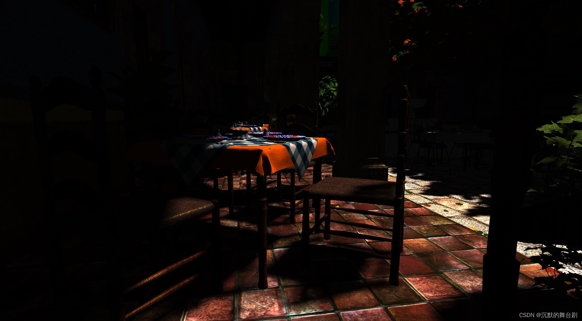
上边片元着色器中可以主要看一下tri_data_to_frag_color函数:此函数是将Visibility Buffer中数据进行转换并索引真实场景数据进行着色的全部流程。
其他过程参照注释即可。经过上述计算可以得到:
三、Visibility Buffer总结
Visibility Buffer 与 G-Buffer的具体对比可以参照以前文章。具体不再赘述,下边主要来看一下Visibility Buffer的优点
3.1 内存带宽
Visibility Buffer方案在带宽消耗上有更大的优势,这一点在高分辨率屏幕,或者在一些高速存储器尺寸受限的情况下(比如只能支持到32位的RT,甚至只能支持屏幕中的部分区域的使用如TBDR架构下的硬件条件)更为明显。
3.2 内存访问模式
shading pass中,我们会根据visibility buffer的数据获得各个像素对应的triangle ID,此时并没有发生顶点属性的读取逻辑,对index buffer以及vertex buffer的真正的读取过程跟一个普通的draw call的实现逻辑差不多,不过这个draw call是覆盖全屏幕的,且数据是全屏幕连续的,并且仅发生一次,而这种数据获取的方式是现代GPU架构friendly的,经过测试发现,这种模式下,对于贴图、VB/IB数据的获取,在L2上可以达到99%的命中率,从而使得整个着色过程十分的高效。
-
相关阅读:
Leetcode 75——1768.交替合并字符串 解题思路与具体代码【C++】
Web前端与其他前端:深度对比与差异性剖析
SpringCloud入门概述;微服务入门概述
NPDP考试倒计时,如何高效提分?
YOLOv2-yolo9000-batter,faster,stronger 论文精度
webpack5识别html中的图片以及将图片打包到对应的文件夹中
AI市场的资本谜团与流向
GitHub私有派生仓库(fork仓库) | 派生仓库改为私有
4.4 Go语言中的单元测试
IP地址定位的特点
- 原文地址:https://blog.csdn.net/qq_35312463/article/details/126050887