-
FPGA——SPI总线控制flash(1)(含代码)
上一篇写了SPI总线的原理,建议先看原理,链接如下:
FPGA——SPI总线详解(概念)_居安士的博客-CSDN博客
这一篇分别来实现SPI总线的flash写使能,读状态
目录
flash写使能
写使能模块要实现控制模块输入start_wr(启动信号)和wren_cmd(写使能指令),写使能信号能把指令输出给spi总线,写使能框图如下:
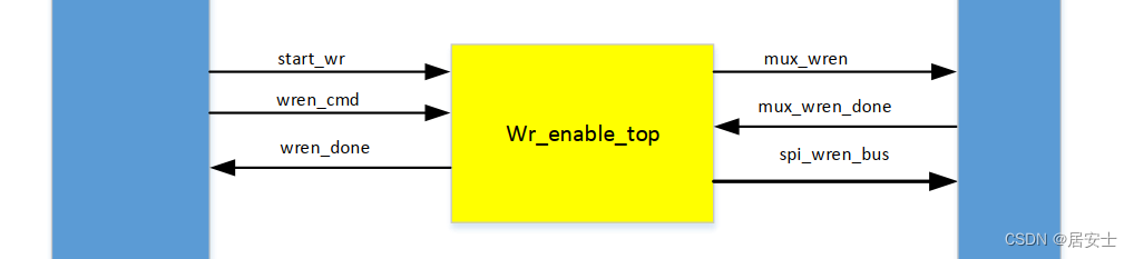
输入输出信号:
名称
输入/输出
位宽
解释
clk_25m
input
1
时钟信号
reset
input
1
复位信号
start_wr
input
1
开始写使能
wren_cmd
input
1
指令信号(0/1)
mux_wren_done
input
1
总线返回信号
mux_wren
output
1
向总线发送请求
(1:开启 0:关闭)
wren_done
output
1
写使能完成
spi_cs
output
1
向总线传输的片选线
spi_clk
output
1
向总线传输的时钟线
spi_dout
output
1
向总线传输的数据线
cnt_wren
reg
3
发送指令个数寄存器(一共8个)
wren_cmd_reg
reg
1
指令缓存
valid_cmd
reg
7
指令寄存器
写使能时序图:
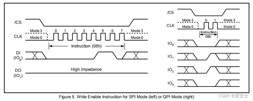
根据时序图,,当片选线拉低了,开始向总线输出DI(06/04),输出clk采集数据,特别需要注意的是,SPI先发送高位数据,且以字节(8bit)为单位去发送
写使能状态机流程图如下:
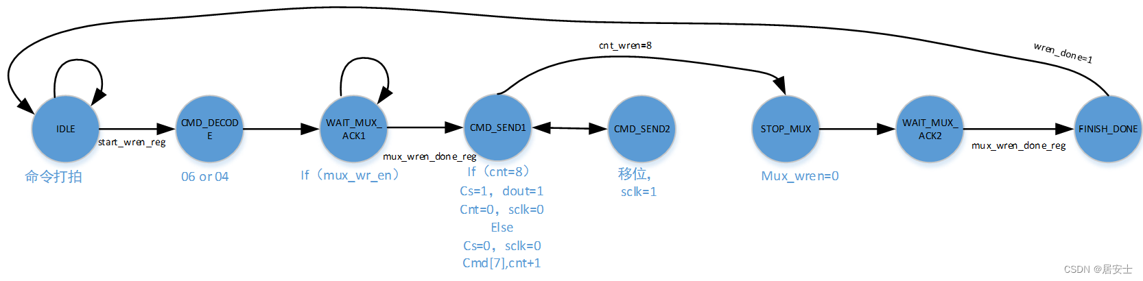 先把输入的start_wr,wren_cmd ,mux_wren_done打一拍
1初始状态下:/cs=1,clk=0,dout=1,wren_cnt=0,vaild_cmd=0,如果start_wr=1则跳转
2指令解析状态:如果指令为0,则输出04;如果指令为1,则输出06,直接跳转
3等待总线应答:向总线发送开始请求,如果应答完成,跳转
4发送状态1:如果cnt==8,发送完成,clk=0,cs拉低,dout=1跳转停止状态;如果没有完成,cnt+1,cs拉低,clk=0,把vaild_cmd[7]给dout,跳转发送状态2
5发送状态2:cs拉低,clk=1把vaild_cmd进行移位,确保每一次都发送的高位
6停止状态:向总线发送停止请求
7等总线应答:如果应答完成,跳转
8完成状态:wren_done=1
代码如下:
- module wr_enable(
- input clk,
- input reset,
- input start_wr,//启动写使能
- input wren_cmd,//写使能命令
- input mux_wren_done,//总线ack
- output reg mux_wren , //启动总线
- output reg spi_cs , //
- output reg spi_clk , //
- output reg spi_dout , //
- output reg wren_done //写使能完成
- );
- reg wren_cmd_reg;
- reg [3:0]cnt_wren;//8位指令计数器
- reg [7:0] cmd_valid;//8位指令
- reg [3:0] state;
- always@(posedge clk)begin
- if(reset)begin
- mux_wren <=1'd0;
- spi_cs <=1'd1;
- spi_clk <=1'd0;
- spi_dout <=1'd1;
- wren_done<=1'd0;
- cnt_wren <=4'd0;
- cmd_valid<=8'd0;
- wren_cmd_reg<=1'd0;
- state <=4'd0;
- end
- else begin
- case(state)
- 4'd0:begin
- if(start_wr)begin
- state <=4'd1;
- wren_cmd_reg<=wren_cmd;//缓存指令:0→ 04h 1→06h
- end
- else begin
- state <=4'd0;
- end
- end
- 4'd1:begin
- case(wren_cmd_reg)
- 0:cmd_valid<=8'h04;
- 1:cmd_valid<=8'h06;
- endcase
- state <=4'd2;
- end
- 4'd2:begin
- mux_wren<=1'd1;
- if(mux_wren_done==1'd1)begin
- state <=4'd3;
- end
- else begin
- state <=4'd2;
- end
- end
- 4'd3:begin
- if(cnt_wren==4'd8)begin
- cnt_wren<=4'd0;//计数器清零
- spi_clk <=1'd0;
- spi_cs <=1'd1;//片选拉低
- spi_dout <=1'd1;
- state <=4'd5;
- end
- else begin
- cnt_wren<=cnt_wren+4'd1;
- spi_clk <=1'd0;//clk=0
- spi_cs <=1'd0;
- spi_dout <=cmd_valid[7];//把最高位给dout
- state <=4'd4;
- end
- end
- 4'd4:begin
- state <=4'd3;
- spi_clk <=1'd1;//clk=1
- spi_cs <=1'd0;
- cmd_valid<={cmd_valid[6:0],1'b0};//移位
- end
- 4'd5:begin
- mux_wren<=1'd0;
- state <=4'd6;
- end
- 4'd6:begin
- if(mux_wren_done==1'd1)begin
- state <=4'd7;
- end
- else begin
- state <=4'd6;
- end
- end
- 4'd7:begin
- wren_done<=1'd1;//发送完成
- state <=4'd0;
- end
- endcase
- end
- end
- endmodule
编写仿真代码:
- module TB_wr_enable(
- );
- reg clk;
- reg reset;
- reg start_wr;
- reg wren_cmd;
- reg mux_wren_done;
- wire mux_wren ;
- wire spi_cs ;
- wire spi_clk ;
- wire spi_dout ;
- wire wren_done;
- wr_enable inst_wr_enable(
- .clk (clk),
- .reset (reset),
- .start_wr (start_wr),//启动写使能
- .wren_cmd (wren_cmd),//写使能命令
- .mux_wren_done(mux_wren_done),//总线ack
- .mux_wren (mux_wren), //启动总线
- .spi_cs (spi_cs), //
- .spi_clk (spi_clk), //
- .spi_dout (spi_dout), //
- .wren_done(wren_done) //写使能完成
- );
- initial begin
- clk=0;
- reset=1;
- #100
- reset=0;
- #1000
- wren_cmd=0;
- start_wr=1;
- #100
- start_wr=0;
- //#100
- //wren_cmd=1;
- //start_wr=1;
- //#100
- //start_wr=0;
- end
- always #20 clk=~clk;
- reg [3:0]state_tb;
- always @(posedge clk)begin
- if(reset)begin
- state_tb<=4'd0;
- mux_wren_done<=1'b0;
- end
- else begin
- mux_wren_done<=1'b0;
- case(state_tb)
- 4'd0:begin
- if(start_wr)
- state_tb<=4'd1;
- end
- 4'd1:begin
- if(mux_wren) begin //请求总线
- state_tb<=4'd2;
- mux_wren_done<=1'b1;
- end
- else begin
- state_tb<=4'd1;
- mux_wren_done<=1'b0;
- end
- end
- 4'd2:begin
- if(!mux_wren) begin //释放总线
- state_tb<=4'd3;
- mux_wren_done<=1'b1;
- end
- else begin
- state_tb<=4'd2;
- mux_wren_done<=1'b0;
- end
- end
- 4'd3:begin
- state_tb<=4'd0;
- mux_wren_done<=1'b0;
- end
- default:begin
- state_tb<=4'd0;
- end
- endcase
- end
- end
- endmodule
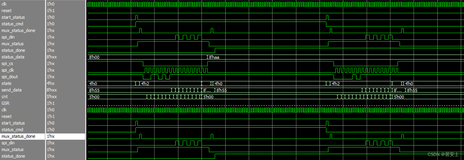
接下来可以看一下仿真的效果,可以看出和数据手册是一致的:
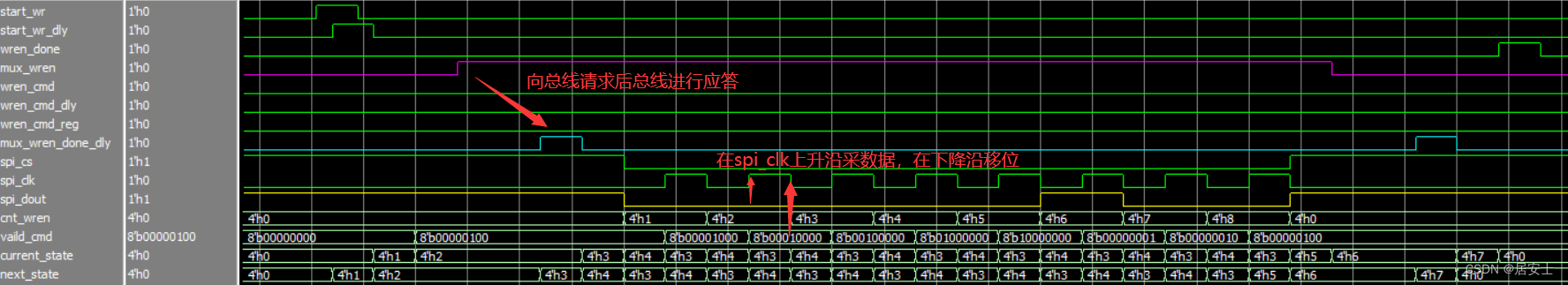
spi_dout输出0000_0100 (04)
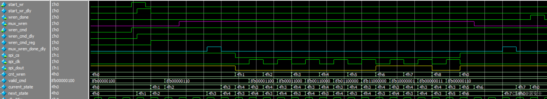
spi_dout输出0000_0110 (06)
flash读状态
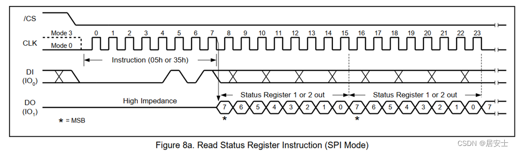
通过将 /CS 驱动为低电平并将状态寄存器 1 的指令代码“05h”或状态寄存器 2 的指令代码“35h”在 CLK 的上升沿移入 DI 引脚来输入指令。 然后,状态寄存器位在 CLK 的下降沿在 DO 引脚上移出,最高有效位 (MSB) 在前,时序图如图所示:
读状态模块图:
和写使能不同的是,多了数据传输
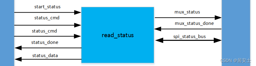
读状态输入输出:
名称
输入/输出
位宽
解释
start_status
input
1
开始读状态
status_cmd
input
1
读状态指令
mux_status_done
input
1
总线返回信号
mux_status
output
1
请求总线
status_done
output
1
读状态完成
status_data
output
8
读取数据
spi_cs
output
1
spi片选线
spi_clk
output
1
spi时钟线
spi_dout
output
1
输入spi
spi_din
input
1
spi输出
cnt_status
reg
8
指令计数器
vaild_cmd
reg
8
指令寄存器
received_data
reg
8
数据寄存器
读状态模块流程图如下:
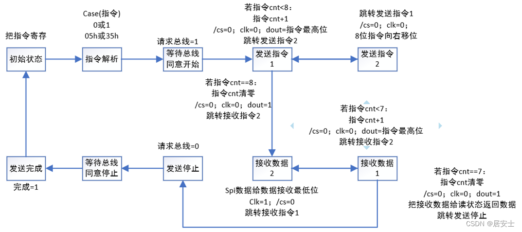
读状态一共有10个状态:
0(初始状态):把0或者1的指令信号进行寄存,防止解析时没有指令信号
1(指令解析):根据0或者1,得到35h或者05h的指令
2(请求总线1):请求开放总线,若应答则跳转
3(发送指令1):得到指令35h或者05h最高位,8位都得到后跳转
4(发送指令2):将指令35h或者05h移位
5(接收数据1):对接收数据进行移位(低位就会移成高位),全部接收后跳转
6(接收数据2):将数据55h(来自读状态寄存器)的最高位给接收数据最低位
7(发送停止):请求关闭总线
8(请求总线2):等待总线应答
9(发送完成):发送完成指令=1
代码如下:
- module read_status(
- input clk ,
- input reset ,
- input start_status ,//开始读状态
- input status_cmd ,//读状态指令
- input mux_status_done ,//总线返回
- input spi_din ,//由总线输入
- output reg mux_status ,//请求总线
- output reg status_done ,//读状态完成
- output reg [7:0] status_data,//读状态返回8位数据
- output reg spi_cs ,//片选信号
- output reg spi_clk ,//时钟信号
- output reg spi_dout //总线输入
- );
- reg [3:0] cnt_status ;//指令计数器
- reg status_cmd_reg ;//指令缓存
- reg [7:0] vaild_cmd ;//指令寄存器
- reg [7:0] received_data;//接收数据
- reg [3:0] state;
- always@(posedge clk)begin
- if(reset)begin
- mux_status <=1'd0;
- status_done <=1'd0;
- status_data <=8'd0;
- spi_cs <=1'd1;
- spi_clk <=1'd0;
- spi_dout <=1'd1;
- cnt_status <=4'd0;
- status_cmd_reg <= 1'd0;
- vaild_cmd <=8'd0;
- received_data <=8'd0;
- state<=4'd0;
- end
- else begin
- case(state)
- 4'd0:begin
- if(start_status)begin
- state<=4'd1;
- status_cmd_reg<=status_cmd;
- end
- else begin
- state<=4'd0;
- end
- end
- 4'd1:begin
- case(status_cmd_reg)
- 1'd0:vaild_cmd<=8'h05;
- 1'd1:vaild_cmd<=8'h35;
- endcase
- mux_status<=1'd1;
- state<=4'd2;
- end
- 4'd2:begin
- if(mux_status_done)begin
- state<=4'd3;
- end
- else begin
- state<=4'd2;
- end
- end
- 4'd3:begin
- if(cnt_status==4'd8)begin
- state<=4'd6;//直接跳转到数据接收2,这样的目的是spi clk可连续
- cnt_status<=4'd0;
- spi_cs <=1'd0;
- spi_clk <=1'd0;
- spi_dout <=1'd1;
- end
- else begin
- cnt_status<=cnt_status+4'd1;
- spi_cs <=1'd0;
- spi_clk <=1'd0;
- spi_dout <=vaild_cmd[7];
- state<=4'd4;
- end
- end
- 4'd4:begin
- state<=4'd3;
- spi_clk <=1'd1;
- spi_cs <=1'd0;
- vaild_cmd<={vaild_cmd[6:0],1'b0};
- end
- 4'd5:begin
- if(cnt_status==4'd8)begin
- state<=4'd7;
- cnt_status<=4'd0;
- spi_cs <=1'd1;
- spi_clk <=1'd0;
- spi_dout <=1'd1;
- status_data<=received_data;
- end
- else begin
- cnt_status<=cnt_status+4'd1;
- spi_cs <=1'd0;
- spi_clk <=1'd0;
- spi_dout <=1'd1;
- received_data<={received_data[6:0],received_data[7]};//received_data最低位移位到最高位
- state<=4'd6;
- end
- end
- 4'd6:begin
- state<=4'd5;
- spi_clk <=1'd1;
- spi_cs <=1'd0;
- received_data[0]<=spi_din;//din给received_data最低位
- end
- 4'd7:begin
- mux_status<=1'd0;
- state<=4'd8;
- end
- 4'd8:begin
- if(mux_status_done)begin
- state<=4'd9;
- end
- else begin
- state<=4'd8;
- end
- end
- 4'd9:begin
- status_done<=1'd1;
- state<=4'd0;
- end
- endcase
- end
- end
- endmodule
TB仿真代码:
- module TB_read_status(
- );
- reg clk ;
- reg reset ;
- reg start_status ;
- reg status_cmd ;
- reg mux_status_done;
- reg spi_din ;
- wire mux_status ;
- wire status_done ;
- wire [7:0] status_data ;
- wire spi_cs ;
- wire spi_clk ;
- wire spi_dout ;
- read_status inst_read_status(
- .clk (clk) ,
- .reset (reset) ,
- .start_status (start_status) ,//开始读状态
- .status_cmd (status_cmd) ,//读状态指令
- .mux_status_done(mux_status_done) ,//总线返回
- .spi_din (spi_din) ,//由总线输入
- .mux_status (mux_status) ,//请求总线
- .status_done (status_done) ,//读状态完成
- .status_data (status_data) ,//读状态返回8位数据
- .spi_cs (spi_cs) ,//片选信号
- .spi_clk (spi_clk) ,//时钟信号
- .spi_dout (spi_dout) //总线输入
- );
- initial begin
- clk=0;
- reset=1;
- start_status=0;
- status_cmd=0;
- #100;
- reset=0;
- #4000
- start_status=1;
- status_cmd=1;
- #40
- start_status=0;
- #4000
- start_status=1;
- status_cmd=0;
- #40
- start_status=0;
- end
- always #20 clk=~clk;
- reg [3:0]state;
- reg [7:0]send_data;
- reg [4:0]cnt;
- always@(posedge clk)begin
- if(reset)begin
- state<=4'd0;
- mux_status_done<=1'd0;
- spi_din<=1'd0;
- send_data<=8'd0;
- cnt<=4'd0;
- end
- else begin
- case(state)
- 4'd0:begin
- spi_din <=1'd0;
- send_data<=8'H55;//发送数据
- cnt<=4'd0;
- if(start_status)begin
- state<=4'd1;
- end
- else begin
- state<=4'd0;
- end
- end
- 4'd1:begin
- if(mux_status==1'd1)begin//通讯开始
- mux_status_done<=1'd1;
- state<=4'd2;
- end
- else begin
- state<=4'd1;
- mux_status_done<=1'd0;
- end
- end
- 4'd2:begin
- mux_status_done<=1'd0;
- if(spi_clk==1'd1)begin
- cnt<=cnt+5'd1;
- end
- else if(cnt==5'd15) begin//16个clk(输出8指令+输入8数据)
- spi_din<=1'd0;
- cnt<=5'd0;
- send_data<=8'd0;
- state<=4'd3;
- end
- else if(cnt>=5'd7)begin//开始接收数据时
- spi_din<=send_data[7];
- send_data<={send_data[6:0],send_data[7]};
- end
- end
- 4'd3:begin
- if(!mux_status)begin//通讯结束
- state<=4'd4;
- mux_status_done<=1'd1;
- end
- else begin
- state<=4'd3;
- mux_status_done<=1'd0;
- end
- end
- 4'd4:begin
- state<=4'd0;
- mux_status_done<=1'd0;
- end
- endcase
- end
- end
- endmodule
仿真结果如下:

flash擦除
擦除分为扇区擦除;32KB擦除;64KB擦除;整片擦除
在擦除之前必须执行写使能命令,除整片擦除外,它们的时序图都是先发送8bit命令代码,再发送24bit地址:
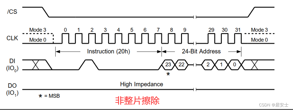
整片擦除,只需要发送8bit命令代码,无需发送24bit地址(因为全擦除成1了)
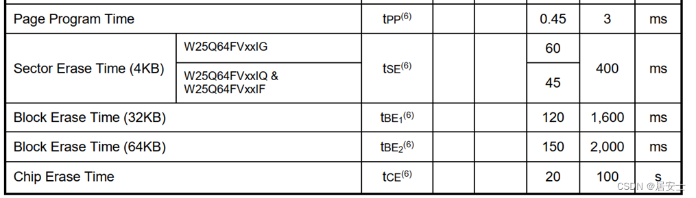 根据数据手册,擦除不同大小的区域,根据不同的擦除指令,需要延时不同时间
1 TSE(擦除扇区) 400ms
2 TE32K(擦除32KB) 1600ms
3 TE64K(擦除64KB) 2000ms
4 TCE(擦除整块) 100s
5 Tpage(页写) 3ms
因此,需要首先编写擦除延时代码,(由于页写也需要延时,因此放在一起)产生上述5个延时完成的信号,代码如下:
- module erase_time(
- input clk,
- input reset,
- input write_en,//页写计时
- input erase_en,//擦除计时
- input [2:0]erase_cmd,//擦除模式选择
- output reg time_done
- );
- reg [2:0] time_mode;//计时模式(4擦除or页写,一共5种)
- reg [31:0]time_cnt ;//擦整片最多100s
- reg [31:0]time_max ;//计时最大值
- reg [3:0]state;
- parameter TSE=20 ;
- parameter TE32K=80 ;
- parameter TE64K=100;
- parameter TCE=1000 ;
- parameter Tpage=15 ;
- always@(posedge clk)begin
- if(reset)begin
- time_done<=1'd0;
- time_cnt<=32'd0;
- time_max<=32'd0;
- time_mode<=3'd0;
- state<=4'd0;
- end
- else begin
- case(state)
- 4'd0:begin
- if(write_en)begin
- time_mode<=3'd5;
- state<=4'd1;
- end
- else if(erase_en)begin
- time_mode<=erase_cmd;//输入的擦除模式
- state<=4'd1;
- end
- else begin
- state<=4'd0;
- end
- end
- 4'd1:begin
- case(time_mode)//根据不同模式分配计数最大值
- 3'd1:time_max<=TSE;
- 3'd2:time_max<=TE32K;
- 3'd3:time_max<=TE64K;
- 3'd4:time_max<=TCE;
- 3'd5:time_max<=Tpage;
- endcase
- state<=4'd2;
- end
- 4'd2:begin
- if(time_max==time_cnt)begin//计数值++
- time_cnt<=32'd0;
- state<=4'd3;
- end
- else begin
- state<=4'd2;
- time_cnt<=time_cnt+32'd1;
- end
- end
- 4'd3:begin
- time_done<=1'd1;
- state<=4'd0;
- end
- endcase
- end
- end
- endmodule
接下来写擦除代码,擦除模块框图如下:
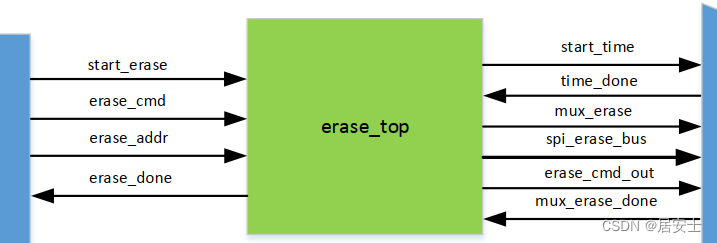
名称
输入输出
位宽
解释
start_erase
input
1
启动擦除模块
erase_cmd
input
3
擦除命令(4种擦除模式)
erase_addr
input
24
擦除地址
mux_erase_done
input
1
总线应答
mux_erase
output
1
请求总线
erase_done
output
1
擦除完成
start_time
output
1
启动擦除计时
time_done
input
1
擦除计时完成
erase_cmd_out
output
3
擦除指令确定计时器计
spi_cs
output
1
spi片选线
spi_clk
output
1
spi时钟线
spi_dout
output
1
spi输出线
擦除流程图如下:
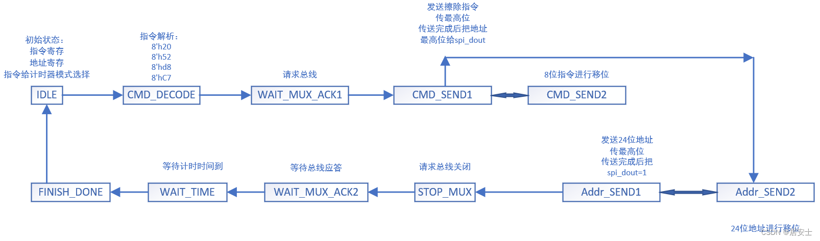
擦除过程:
0(初始状态):把页写突发长度和页写地址寄存
1(指令解析):把02h给指令寄存器
2(请求总线):请求打开总线
3(发送指令1):把指令最高位给spi_dout,移完8位把地址最高位给spi_dout
4(发送指令2):移位8位指令
5(发送地址1):把地址最高位给spi_dout,移完24位把数据最高位给spi_dout
6(发送地址2):移位24位地址
7(计数发送数据):判断cnt_byte是否等于突发长度
8(停止):请求总线停止
- module erase_top(
- input clk,
- input reset,
- input start_erase ,
- input [2:0] erase_cmd ,//擦除指令(1234)
- input [23:0]erase_addr ,//擦除地址
- input mux_erase_done ,//擦除总线ack
- input time_done ,//计时完成
- output reg mux_erase ,//擦除总线请求
- output reg spi_cs ,
- output reg spi_clk ,
- output reg spi_dout ,
- output reg erase_done,//擦除完成
- output reg erase_en
- );
- erase_time inst_erase_time(
- .clk (clk),
- .reset (reset),
- .write_en (),//页写计时
- .erase_en (erase_en),//擦除计时
- .erase_cmd(erase_cmd),//擦除模式选择
- .time_done(time_done)
- );
- reg [5:0] cnt;
- reg[7:0] valid_cmd ;//8位指令寄存器
- reg[2:0] erase_cmd_reg ; //指令寄存
- reg[23:0]erase_addr_reg; //地址寄存
- reg [3:0] state;
- always@(posedge clk)begin
- if(reset)begin
- mux_erase <=1'd0;
- spi_cs <=1'd1;
- spi_clk <=1'd0;
- spi_dout <=1'd1;
- erase_done<=1'd0;
- cnt <=6'd0;
- valid_cmd <=8'd0;
- erase_cmd_reg <=3'd0;
- erase_addr_reg<=24'd0;
- erase_en <=1'd0;
- state<=4'd0;
- end
- else begin
- case(state)
- 4'd0:begin
- if(start_erase)begin
- erase_cmd_reg<=erase_cmd;
- erase_addr_reg<=erase_addr;
- state<=4'd1;
- end
- else begin
- state<=4'd0;
- end
- end
- 4'd1:begin
- case(erase_cmd_reg)//指令1234对应的8位命令
- 3'D1: valid_cmd <= 8'h20;
- 3'D2: valid_cmd <= 8'h52;
- 3'D3: valid_cmd <= 8'hd8;
- 3'D4: valid_cmd <= 8'hC7;
- endcase
- state<=4'd2;
- end
- 4'd2:begin
- mux_erase<=1'd1;
- if(mux_erase_done)begin
- state<=4'd3;
- erase_en<=1'd1;//与总线请求通讯后开始计时
- end
- else begin
- state<=4'd2;
- end
- end
- 4'd3:begin
- erase_en<=1'd0;
- if(cnt==6'd8)begin
- cnt<=6'd0;
- spi_cs <=1'd0;
- spi_clk <=1'd0;
- spi_dout <=1'd1;
- state<=4'd6;
- end
- else begin
- cnt<=cnt+6'd1;
- spi_cs <=1'd0;
- spi_clk <=1'd0;
- spi_dout <=valid_cmd[7];
- state<=4'd4;
- end
- end
- 4'd4:begin
- spi_cs <=1'd0;
- spi_clk <=1'd1;
- valid_cmd<={valid_cmd[6:0],valid_cmd[7]};
- state<=4'd3;
- end
- 4'd5:begin
- if(cnt==6'd23)begin
- cnt<=6'd0;
- spi_cs <=1'd1;
- spi_clk <=1'd0;
- spi_dout <=erase_addr_reg[23];
- state<=4'd7;
- end
- else begin
- cnt<=cnt+6'd1;
- spi_cs <=1'd0;
- spi_clk <=1'd0;
- spi_dout <=erase_addr_reg[23];
- state<=4'd6;
- end
- end
- 4'd6:begin
- spi_cs <=1'd0;
- spi_clk <=1'd1;
- erase_addr_reg<={erase_addr_reg[22:0],1'b0};
- state<=4'd5;
- end
- 4'd7:begin
- mux_erase<=1'd1;
- state<=4'd8;
- end
- 4'd8:begin
- if(mux_erase_done)begin
- state<=4'd9;
- end
- else begin
- state<=4'd8;
- end
- end
- 4'd9:begin
- if(time_done)begin//延时的时间到了
- state<=4'd10;
- end
- else begin
- state<=4'd9;
- end
- end
- 4'd10:begin
- erase_done<=1'd0;
- state<=4'd0;
- end
- endcase
- end
- end
- endmodule
编写仿真TB代码:
- module TB_erase_top(
- );
- reg clk ;
- reg reset ;
- reg start_erase ;
- reg [2:0] erase_cmd ;//擦除指令
- reg [23:0]erase_addr ;//擦除地址
- reg mux_erase_done ;
- wire time_done ;//计时完成
- wire mux_erase ;
- wire spi_cs ;
- wire spi_clk ;
- wire spi_dout ;
- wire erase_done;
- wire erase_en;
- erase_top erase_top(
- .clk (clk) ,
- .reset (reset) ,
- .start_erase (start_erase) ,
- .erase_cmd (erase_cmd) ,//擦除指令
- .erase_addr (erase_addr) ,//擦除地址
- .mux_erase_done (mux_erase_done) ,
- .time_done (time_done) ,//计时完成
- .mux_erase (mux_erase) ,
- .spi_cs (spi_cs) ,
- .spi_clk (spi_clk) ,
- .spi_dout (spi_dout) ,
- .erase_done (erase_done) ,
- .erase_en (erase_en)
- );
- initial begin
- clk =0;
- reset =1;
- start_erase =0; //擦除启动信号
- erase_cmd =0; //擦除命令数据2位
- erase_addr =0; //擦除地址
- #1000;
- reset =0;
- #1000;
- start_erase =1; //擦除启动信号
- erase_cmd =1; //擦除命令数据2位
- erase_addr =24'haaaa55; //擦除地址
- #40;
- start_erase =0; //擦除启动信号
- erase_cmd =0; //擦除命令数据2位
- erase_addr =0; //擦除地址
- end
- always #20 clk= ~clk;
- reg [2:0] state;
- always @(posedge clk)begin
- if(reset)begin
- state <= 3'd0;
- mux_erase_done<=1'b0;
- end
- else begin
- case (state)
- 3'd0:begin
- if(mux_erase)begin
- state <= 3'd1;
- mux_erase_done<=1'b1;
- end
- else begin
- state <= 3'd0;
- mux_erase_done<=1'b0;
- end
- end
- 3'd1:begin
- state <= 3'd2;
- mux_erase_done<=1'b0;
- end
- 3'd2:begin
- if(!mux_erase)begin
- state <= 3'd3;
- mux_erase_done<=1'b1;
- end
- else begin
- state <= 3'd2;
- mux_erase_done<=1'b0;
- end
- end
- 3'd3:begin
- mux_erase_done<=1'b0;
- state <= 3'd0;
- end
- default :state <= 3'd0;
- endcase
- end
- end
- endmodule
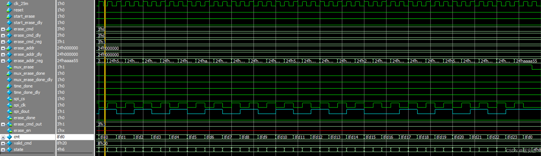
仿真图如下:
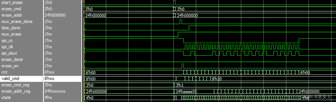
传擦除模式1(02h)指令
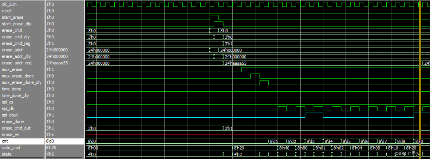
传擦除地址
-
相关阅读:
SEO与社交媒体的关系
130. 被围绕的区域
Linux系统
考研数据结构大题整合_组二(TJP组)
Room (三) RecyclerView 呈现列表数据
c单元语言测试--自定义代码、rspec 和Google test
个人信贷违约预测代码实战
java计算机毕业设计springboot+vue南天在线求助系统
2023_Spark_实验十一:RDD高级算子操作
HCIP学习笔记
- 原文地址:https://blog.csdn.net/weixin_46188211/article/details/125884831
