-
linux 设备树学习总结
本篇文档是基于韦东山老师的设备树专题学习总结而来。
linux 设备树学习总结
1 linux引入设备树的原因以及设备驱动实现方法
linux引入设备树是有历史缘由的,原始的linux设备驱动编写方法不是将设备资源固定在代码中就是通过总线设备资源的方式固定在对应设备的.c文件中,通过注册设备而向系统注册设备资源。
这两种方法都不太符合linus对linux的软件架构的设想,也不符合现代软件的设计思想。
下面的介绍以字符设备驱动来介绍(以韦东山老师的视频为基础介绍)1.1 设备驱动的编写方法简介
设备驱动的编写方法:传统方法,总线设备驱动模型方法、驱动设备树方法
1.1.1 传统方法:
传统驱动方法编写驱动的特定:
- 分配,设置,注册file_operations结构体(
.open, .read, .write, .ioctl等成员) - 硬件资源固定在代码中,代码编写非常简单,但是代码的扩展性很差,当资源发生变动时就需要去查阅硬件手册,去修改对应的设备驱动代码实现资源的更新。
1.1.2 总线设备驱动模型方法:
总线设备驱动模型编写驱动的特定:
- 分配,设置,注册file_operations结构体(
.open, .read, .write, .ioctl等成员) - 通过该方法实现的驱动程序被分为两部分,一部分是设备驱动
xxx_drv.c,另一部分是设备资源xxx_dev.c,这两部分都是.c文件的形式存在,在编写设备驱动的时候会讲设备资源以resource的形式固定在设备文件中,然后注册设备和驱动,获取资源的时候通过总线设备去获取对应的资源。 - 更新设备资源的时候可以去修改对应的
xxx_dev.c文件,易于扩展功能,缺点是每次修改对应的xxx_dev.c文件都需要重新编译内核烧录到板子上重新运行。
1.1.3 驱动设备树方法:
- 分配,设置,注册file_operations结构体(
.open, .read, .write, .ioctl等成员) - 和总线设备驱动模型一样,驱动程序分为两部分:设备驱动
xxx_drv.c,xxx.dts。 - 设备树xxx.dts文件定义了设备需要的资源,功能扩展非常容易,当硬件发生变动时,只需要修改对应的
xxx.dts文件即可,重新编译设备文件替换原来的DTB文件即可,而linux内核不需要重新编译。 - dts文件被编译为dtb文件, 然后传给内核,内核解析dtb文件,构建对应的device_node。
1.2 字符设备驱动的传统写法
- 分配,设置,注册file_operations结构体(
.open, .read, .write, .ioctl等成员),实现.open, .read, .write, .ioctl这些接口,这些接口通过操作对应的硬件去实现对应的功能。 - major = register_chrdev(0, name, &file_operations);
- char_class = class_create(THIS_MODULE, name);
- device_create(char_class, NULL, MKDEV(major, 0), NULL, name); /* /dev/name */
韦东山老师给出的示例代码如下所示:
static struct file_operations myled_oprs = { .owner = THIS_MODULE, .open = led_open, .write = led_write, .release = led_release, }; static int myled_init(void) { major = register_chrdev(0, "myled", &myled_oprs); led_class = class_create(THIS_MODULE, "myled"); device_create(led_class, NULL, MKDEV(major, 0), NULL, "led"); /* /dev/led */ return 0; } static void myled_exit(void) { unregister_chrdev(major, "myled"); device_destroy(led_class, MKDEV(major, 0)); class_destroy(led_class); } module_init(myled_init); module_exit(myled_exit); MODULE_LICENSE("GPL");- 1
- 2
- 3
- 4
- 5
- 6
- 7
- 8
- 9
- 10
- 11
- 12
- 13
- 14
- 15
- 16
- 17
- 18
- 19
- 20
- 21
- 22
- 23
- 24
- 25
- 26
- 27
- 28
关于module_init的相关处理可以参考:Linux Driver 和Device匹配过程分析
1.3 总线设备驱动模型写法
- 使用总线设备驱动模型会将驱动程序分为两部分,xxx_drv.c和xxx_dev.c,两个文件分别对应着platform_driver和platform_device。
- platform_driver : 根据与之匹配的platform_device获得硬件资源, 并分配/设置/注册file_operations
- platform_device : 指定硬件资源, 来自xxx.c文件
1.3.1 xxx_drv.c
1.3.1.1 驱动程序流程
- platform_get_resource(platform_device, IORESOURCE_MEM, 0);
- 在
xxx_probe函数里面分配,设置,注册file_operations结构体(.open, .read, .write, .ioctl等成员),实现.open, .read, .write, .ioctl这些接口,这些接口通过操作对应的硬件去实现对应的功能。- major = register_chrdev(0, “xxx”, &file_operations);
- char_class = class_create(THIS_MODULE, name);
- device_create(char_class, NULL, MKDEV(major, 0), NULL, “xxx”); /* /dev/name */
- 将设备驱动注册到对应的总线驱动里面
struct platform_driver xxx_drv = { .probe = xxx_probe, .remove = xxx_remove, .driver = { .name = "xxx", } };- 1
- 2
- 3
- 4
- 5
- 6
- 7
- platform_driver_register(&xxx_drv);
1.3.1.2 韦东山老师驱动示例
下面是韦东山老师在讲课时给出的示例:
static struct file_operations myled_oprs = { .owner = THIS_MODULE, .open = led_open, .write = led_write, .release = led_release, }; static int led_probe(struct platform_device *pdev) { struct resource *res; /* 根据platform_device的资源进行ioremap */ res = platform_get_resource(pdev, IORESOURCE_MEM, 0); led_pin = res->start; major = register_chrdev(0, "myled", &myled_oprs); led_class = class_create(THIS_MODULE, "myled"); device_create(led_class, NULL, MKDEV(major, 0), NULL, "led"); /* /dev/led */ return 0; } static int led_remove(struct platform_device *pdev) { unregister_chrdev(major, "myled"); device_destroy(led_class, MKDEV(major, 0)); class_destroy(led_class); return 0; } struct platform_driver led_drv = { .probe = led_probe, .remove = led_remove, .driver = { .name = "myled", } }; static int myled_init(void) { platform_driver_register(&led_drv); return 0; } static void myled_exit(void) { platform_driver_unregister(&led_drv); } module_init(myled_init); module_exit(myled_exit); MODULE_LICENSE("GPL");- 1
- 2
- 3
- 4
- 5
- 6
- 7
- 8
- 9
- 10
- 11
- 12
- 13
- 14
- 15
- 16
- 17
- 18
- 19
- 20
- 21
- 22
- 23
- 24
- 25
- 26
- 27
- 28
- 29
- 30
- 31
- 32
- 33
- 34
- 35
- 36
- 37
- 38
- 39
- 40
- 41
- 42
- 43
- 44
- 45
- 46
- 47
- 48
- 49
- 50
- 51
- 52
- 53
- 54
- 55
1.3.2 xxx_dev.c
1.3.2.1 驱动程序流程
- 在xxx_dev.c文件中分配/设置/注册一个platform_device
static struct resource xxx_resource[] = { [0] = { .start = xxx_start_res0, .end = xxx_end_res0, .flags = IORESOURCE_MEM, }, }; static struct platform_device led_dev = { .name = "xxx", .id = -1, .num_resources = ARRAY_SIZE(xxx_resource), .resource = xxx_resource, .dev = { .release = xxx_release, }, };- 1
- 2
- 3
- 4
- 5
- 6
- 7
- 8
- 9
- 10
- 11
- 12
- 13
- 14
- 15
- 16
- 注册设备platform_device_register(&xxx_dev)
1.3.2.1 韦东山老师设备注册示例
下面是韦东山老师在讲课时给出的示例:
static struct resource led_resource[] = { [0] = { .start = S3C2440_GPF(5), .end = S3C2440_GPF(5), .flags = IORESOURCE_MEM, }, }; static void led_release(struct device * dev) { } static struct platform_device led_dev = { .name = "myled", .id = -1, .num_resources = ARRAY_SIZE(led_resource), .resource = led_resource, .dev = { .release = led_release, }, }; static int led_dev_init(void) { platform_device_register(&led_dev); return 0; } static void led_dev_exit(void) { platform_device_unregister(&led_dev); } module_init(led_dev_init); module_exit(led_dev_exit); MODULE_LICENSE("GPL");- 1
- 2
- 3
- 4
- 5
- 6
- 7
- 8
- 9
- 10
- 11
- 12
- 13
- 14
- 15
- 16
- 17
- 18
- 19
- 20
- 21
- 22
- 23
- 24
- 25
- 26
- 27
- 28
- 29
- 30
- 31
- 32
- 33
- 34
- 35
- 36
- 37
1.4 驱动设备树方法
驱动设备树的编写方法和总线设备驱动模型相似,不同的是platform_device的资源放置到了xxx.dts文件中。
1.4.1 xxx_drv.c
1.4.1.1 驱动程序流程
- of_property_read_s32等fdt接口去获取对应的资源
- 在
xxx_probe函数里面分配,设置,注册file_operations结构体(.open, .read, .write, .ioctl等成员),实现.open, .read, .write, .ioctl这些接口,这些接口通过操作对应的硬件去实现对应的功能。- major = register_chrdev(0, “xxx”, &file_operations);
- char_class = class_create(THIS_MODULE, name);
- device_create(char_class, NULL, MKDEV(major, 0), NULL, “xxx”); /* /dev/name */
- 将设备驱动注册到对应的总线驱动里面
- 在struct of_device_id里面添加对应的设备驱动支持的设备列表。
struct platform_driver xxx_drv = { .probe = xxx_probe, .remove = xxx_remove, .driver = { .name = "xxx", } };- 1
- 2
- 3
- 4
- 5
- 6
- 7
- platform_driver_register(&xxx_drv);
1.4.1.2 韦东山老师驱动示例
下面是韦东山老师在讲课时给出的示例:
static struct file_operations myled_oprs = { .owner = THIS_MODULE, .open = led_open, .write = led_write, .release = led_release, }; static int led_probe(struct platform_device *pdev) { struct resource *res; /* 根据platform_device的资源进行ioremap */ res = platform_get_resource(pdev, IORESOURCE_MEM, 0); if (res) { led_pin = res->start; } else { /* 获得pin属性 */ of_property_read_s32(pdev->dev.of_node, "pin", &led_pin); } if (!led_pin) { printk("can not get pin for led\n"); return -EINVAL; } major = register_chrdev(0, "myled", &myled_oprs); led_class = class_create(THIS_MODULE, "myled"); device_create(led_class, NULL, MKDEV(major, 0), NULL, "led"); /* /dev/led */ return 0; } static int led_remove(struct platform_device *pdev) { unregister_chrdev(major, "myled"); device_destroy(led_class, MKDEV(major, 0)); class_destroy(led_class); return 0; } static const struct of_device_id of_match_leds[] = { { .compatible = "jz2440_led", .data = NULL }, { /* sentinel */ } }; struct platform_driver led_drv = { .probe = led_probe, .remove = led_remove, .driver = { .name = "myled", .of_match_table = of_match_leds, /* 能支持哪些来自于dts的platform_device */ } }; static int myled_init(void) { platform_driver_register(&led_drv); return 0; } static void myled_exit(void) { platform_driver_unregister(&led_drv); } module_init(myled_init); module_exit(myled_exit); MODULE_LICENSE("GPL");- 1
- 2
- 3
- 4
- 5
- 6
- 7
- 8
- 9
- 10
- 11
- 12
- 13
- 14
- 15
- 16
- 17
- 18
- 19
- 20
- 21
- 22
- 23
- 24
- 25
- 26
- 27
- 28
- 29
- 30
- 31
- 32
- 33
- 34
- 35
- 36
- 37
- 38
- 39
- 40
- 41
- 42
- 43
- 44
- 45
- 46
- 47
- 48
- 49
- 50
- 51
- 52
- 53
- 54
- 55
- 56
- 57
- 58
- 59
- 60
- 61
- 62
- 63
- 64
- 65
- 66
- 67
- 68
- 69
- 70
- 71
- 72
- 73
1.4.2 xxx.dts
韦东山老师给出的设备树代码:
/* * SAMSUNG SMDK2440 board device tree source * * Copyright (c) 2018 weidongshan@qq.com * dtc -I dtb -O dts -o jz2440.dts jz2440.dtb */ #define S3C2410_GPA(_nr) ((0<<16) + (_nr)) #define S3C2410_GPB(_nr) ((1<<16) + (_nr)) #define S3C2410_GPC(_nr) ((2<<16) + (_nr)) #define S3C2410_GPD(_nr) ((3<<16) + (_nr)) #define S3C2410_GPE(_nr) ((4<<16) + (_nr)) #define S3C2410_GPF(_nr) ((5<<16) + (_nr)) #define S3C2410_GPG(_nr) ((6<<16) + (_nr)) #define S3C2410_GPH(_nr) ((7<<16) + (_nr)) #define S3C2410_GPJ(_nr) ((8<<16) + (_nr)) #define S3C2410_GPK(_nr) ((9<<16) + (_nr)) #define S3C2410_GPL(_nr) ((10<<16) + (_nr)) #define S3C2410_GPM(_nr) ((11<<16) + (_nr)) /dts-v1/; / { model = "SMDK24440"; compatible = "samsung,smdk2440"; #address-cells = <1>; #size-cells = <1>; memory@30000000 { device_type = "memory"; reg = <0x30000000 0x4000000>; }; /* cpus { cpu { compatible = "arm,arm926ej-s"; }; }; */ chosen { bootargs = "noinitrd root=/dev/mtdblock4 rw init=/linuxrc console=ttySAC0,115200"; }; led { compatible = "jz2440_led"; pin = <S3C2410_GPF(5)>; }; };- 1
- 2
- 3
- 4
- 5
- 6
- 7
- 8
- 9
- 10
- 11
- 12
- 13
- 14
- 15
- 16
- 17
- 18
- 19
- 20
- 21
- 22
- 23
- 24
- 25
- 26
- 27
- 28
- 29
- 30
- 31
- 32
- 33
- 34
- 35
- 36
- 37
- 38
- 39
- 40
- 41
- 42
- 43
- 44
- 45
- 46
- 47
- 48
- 49
2 设备树规范
2.1 设备树规范参考资料
The Devicetree Source (DTS) format is a textual representation of a devicetree in a form that can be processed by dtc into a binary devicetree in the form expected by the kernel.
2.1.1 linux内核
Documentation/devicetree/bindings/- 1
2.1.2 设备树官方文档
devicetree-specification-v0.3.pdf
官方文档下载地址:2.2 DTS设备树规范
2.2.1 节点和属性定义
设计对象节点用node-name和unit-address定义,用大括号标记节点定义的开始和结束。在它们之前可能会有label。
[label:] node-name[@unit-address] { [properties definitions] [child nodes] };- 1
- 2
- 3
- 4
节点可以包含属性定义和/或子节点定义。如果两者都存在,那么属性应该出现在子节点之前。
2.2.2 属性定义
2.2.2.1 名称值对
- 属性定义是以下形式中的名称值对:
[label:] property-name = value;- 1
2.2.2.2 零长度值的属性
- 具有空(零长度)值的属性,其格式为:
[label:] property-name;- 1
2.2.2.3 删除先前定义的属性
- 可以删除先前定义的属性:
/delete-property/ property-name;- 1
2.2.3 属性值定义以及算术、按位或逻辑表达式
2.2.3.1 32位整数单元格的数组
- 属性值可以定义为32位整数单元格的数组,以及以空结尾的字符串或字节字符串的组合。
- 单元格数组用围绕着一个用空间分隔的C语言类型的整数列表的三角括号表示,样例
interrupts = <0 17 0xc>; /*interrupts的三个整数分别表示中断类型(SPI/PPI/SGI),中断ID,以及中断触发类型 */- 1
- 值可以用括号内的算术、按位或逻辑表达式表示。
2.2.3.2 算术运算符
Arithmetic operators(算术运算符) + add - subtract * multiply / divide- 1
- 2
- 3
- 4
- 5
2.2.3.3 位运算符
Bitwise operators(位运算符) & and | or ^ exclusive or ~ not << left shift >> right shift- 1
- 2
- 3
- 4
- 5
- 6
- 7
2.2.3.4 逻辑运算符
Logical operators(逻辑运算符) && and || or ! not- 1
- 2
- 3
- 4
2.2.3.5 关系运算符
Relational operators(关系运算符) < less than > greater than <= less than or equal >= greater than or equal == equal != not equal- 1
- 2
- 3
- 4
- 5
- 6
- 7
2.2.3.6 三元运算符
Ternary operators(三元运算符) ?: (condition ? value_if_true : value_if_false)- 1
- 2
2.2.3.7 64位的值
一个64位的值用两个32位的单元格来表示
clock-frequency = <0x00000001 0x00000000>;- 1
2.2.3.8 字符串值
使用双引号以终止结尾的字符串值表示(属性值被认为包含终止NULL字符)。
compatible = "simple-bus";- 1
2.2.3.9 字节字符串
一个字节字符串用方括号括起来,每个字节用两个十六进制数字表示。每个字节之间的空格都是可选的。
local-mac-address = [00 00 12 34 56 78];- 1
or
local-mac-address = [000012345678];- 1
2.2.3.10 组合组件
值可以有几个用逗号分隔的组合组件,它们被连接在一起
compatible = "ns16550", "ns8250"; example = <0xf00f0000 19>, "a strange property format";- 1
- 2
2.2.3.11 对其他节点的引用
在单元格数组中,对另一个节点的引用将扩展到该节点的扇柄。引用可以在后面跟着节点的标签。
interrupt-parent = < &mpic >; /* mpic 是label */- 1
或者它们可以是括号中节点的完整路径
interrupt-parent = < &{/soc/interrupt-controller@40000} >;- 1
2.2.3.12 对其他节点的引用
在单元格数组之外,对另一个节点的引用将扩展到该节点的完整路径。
ethernet0 = &EMAC0;- 1
2.2.3.13 标签的使用
标签也可以出现在属性值的任何组件之前或之后,或单元格数组的单元格之间,或字节字符串的字节之间
reg = reglabel: <0 sizelabel: 0x1000000>; prop = [ab cd ef byte4: 00 ff fe]; str = start: "string value" end: ;- 1
- 2
- 3
2.2.4 DTS文件布局
The /dts-v1/; shall be present to identify the file as a version 1 DTS (dts files without this tag will be treated by dtc as being in the obsolete version 0, which uses a different format for integers in addition to other small but incompatible changes).- 1
- 2
/dts-v1/;应将文件标识为版本1 DTS(没有此标记的dts文件将被dtc视为过时版本0,该版本除了使用其他小但不兼容的更改外,还使用不同的整数格式)。
Memory reservations define an entry for the devicetree blob’s memory reservation table. They have the form: e.g., /memreserve/ <address> <length>; Where <address> and <length> are 64-bit C-style integers.- 1
- 2
• The / { }; section defines the root node of the devicetree.
• C style (/* . . . */) and C++ style (//) comments are supported./dts-v1/; [memory reservations] / { [property definitions] [child nodes] };- 1
- 2
- 3
- 4
- 5
- 6
2.2.5 特殊的、默认的属性
2.2.5.1 根节点
#address-cells // 在它的子节点的reg属性中, 使用多少个u32整数来描述地址(address)
#size-cells // 在它的子节点的reg属性中, 使用多少个u32整数来描述大小(size)
compatible // 定义一系列的字符串, 用来指定内核中哪个machine_desc可以支持本设备
// 即这个板子兼容哪些平台
// uImage : smdk2410 smdk2440 mini2440 ==> machine_descmodel // 咱这个板子是什么
// 比如有2款板子配置基本一致, 它们的compatible是一样的
// 那么就通过model来分辨这2款板子2.2.5.2 /memory节点
device_type = "memory"; reg // 用来指定内存的地址、大小- 1
- 2
2.2.5.3 /chosen节点
/chosen bootargs // 内核command line参数, 跟u-boot中设置的bootargs作用一样- 1
- 2
2.2.5.4 /cpus节点
/cpus
/cpus节点下有1个或多个cpu子节点, cpu子节点中用reg属性用来标明自己是哪一个cpu
所以 /cpus 中有以下2个属性:- #address-cells // 在它的子节点的reg属性中, 使用多少个u32整数来描述地址(address)
- #size-cells // 在它的子节点的reg属性中, 使用多少个u32整数来描述大小(size) 必须设置为0
- /cpus/cpu* device_type = “cpu”; reg // 表明自己是哪一个cpu
2.2.6 引用其他节点
该部分和前面介绍的
2.2.3.11 对其他节点的引用是一样的,2.2.6.1 phandle
- phandle : // 节点中的phandle属性, 它的取值必须是唯一的(不要跟其他的phandle值一样)
pic@10000000 { phandle = <1>; interrupt-controller; }; another-device-node { interrupt-parent = <1>; // 使用phandle值为1来引用上述节点 };- 1
- 2
- 3
- 4
- 5
- 6
- 7
- 8
2.2.6.2 label:
PIC: pic@10000000 { interrupt-controller; }; another-device-node { interrupt-parent = <&PIC>; // 使用label来引用上述节点, // 使用lable时实际上也是使用phandle来引用, // 在编译dts文件为dtb文件时, 编译器dtc会在dtb中插入phandle属性 };- 1
- 2
- 3
- 4
- 5
- 6
- 7
- 8
- 9
2.3 DTB设备树规范
The Devicetree Blob (DTB) format is a flat binary encoding of devicetree data. It used to exchange devicetree data between software programs. For example, when booting an operating system, firmware will pass a DTB to the OS kernel. note:On most Open Firmware compliant platforms the devicetree is extracted by calling firmware methods to walk through the tree structure.- 1
- 2
- 3
设备Blob(DTB)格式是设备数据的平面二进制编码。它用于在软件程序之间交换设备的数据。例如,当启动操作系统时,固件将将DTB传递给OS内核。
在大多数开放固件兼容的平台上,通过调用固件方法(of_xxx)遍历树结构来提取设备资源数据。2.3.1 设备树.dtb格式
官方给的设备树.dtb格式的说明
The DTB format encodes the devicetree data within a single, linear, pointerless data structure. It consists of a small header (see section 5.2), followed by three variable sized sections: the memory reservation block (see section 5.3), the structure block (see secton 5.4), and the strings block (see section 5.5). These should be present in the flattened devicetree in that order. Thus, the devicetree structure as a whole, when loaded into memory at address, will resemble the diagram in Fig. 5.1 (lower addresses are at the top of the diagram).- 1
- 2
- 3
- 4
- 5

The (free space) sections may not be present, though in some cases they might be required to satisfy the alignment constraints of the individual blocks- 1
- 2
2.3.2 .dtb struct ftd_header
The layout of the header for the devicetree is defined by the following C structure. All the header fields are 32-bit integers, stored in big-endian format. 设备的头布局由以下C结构定义。所有的头字段都是32位整数,以大端点格式存储。- 1
- 2
- 3
下面将介绍设备树DTB 的格式,同时以韦东山老师上课给出的示例DTB文件为例去解析对应的结构。
2.3.2.1 struct fdt_header
struct fdt_header { uint32_t magic; uint32_t totalsize; uint32_t off_dt_struct; uint32_t off_dt_strings; uint32_t off_mem_rsvmap; uint32_t version; uint32_t last_comp_version; uint32_t boot_cpuid_phys; uint32_t size_dt_strings; uint32_t size_dt_struct; };- 1
- 2
- 3
- 4
- 5
- 6
- 7
- 8
- 9
- 10
- 11
- 12
2.3.2.2 magic
magic This field shall contain the value `0xd00dfeed` (big-endian).- 1
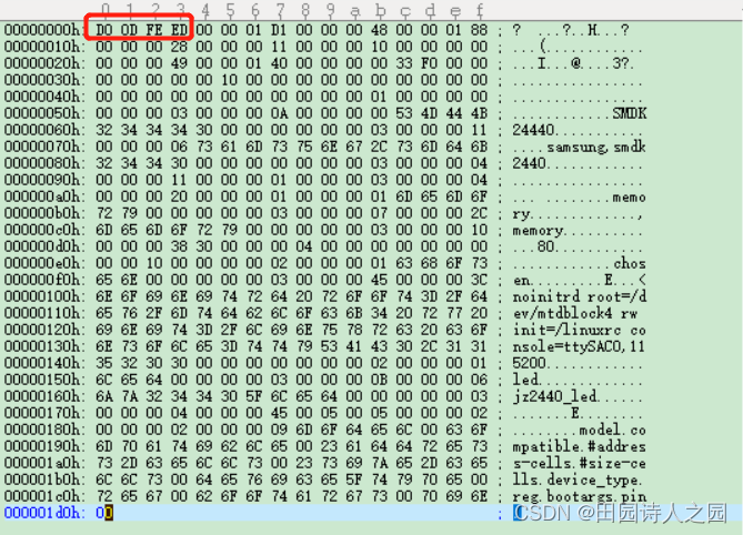
下面对应的dtb文件的magic是0xdoodfeed
2.3.2.3 totalsize
totalsize This field shall contain the total size in bytes of the devicetree data structure. This size shall encompass all sections of the structure: the header, the memory reservation block, structure block and strings block, as well as any free space gaps between the blocks or after the final block.- 1
- 2
- 3
此字段应包含设备树数据结构的字节总大小。此尺寸应包括结构的所有部分:头部、内存保留块、结构块和字符串块,以及块之间或最终块之后的任何自由空间间隙。
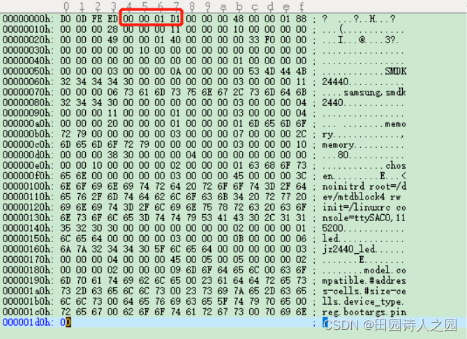
下面看对应的totalsize的大小为0x0001d1,大小为465 Bytes

2.3.2.4 off_dt_struct
off_dt_struct This field shall contain the offset in bytes of the structure block (see section 5.4) from the beginning of the header.- 1
- 2
该字段应包含结构块(structure block)开始的字节偏移量,即从该位置开始后面的内容是结构快的数据。
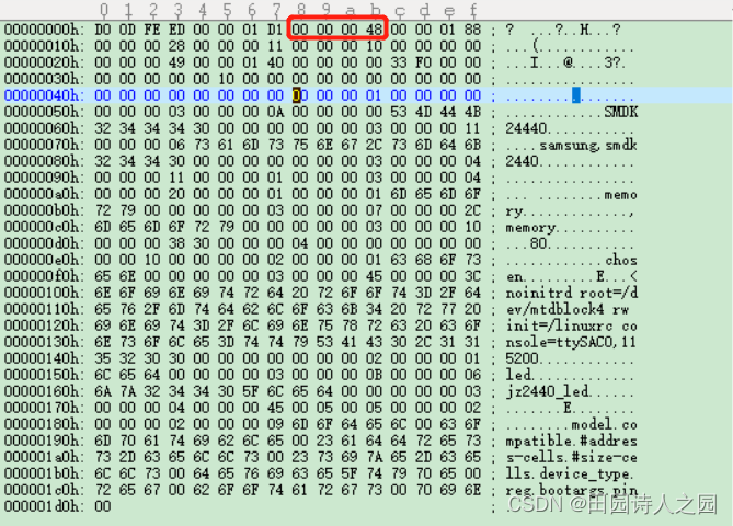
由下图可以看出off_dt_struct 的值为0x00000048,表示的是structure block的起始地址为0x00000048。
off_dt_struct 和size_dt_struct配对使用,分别用来表示 structure block的起始地址和大小。
2.3.2.5 off_dt_strings
off_dt_strings This field shall contain the offset in bytes of the strings block (see section 5.5) from the beginning of the header.- 1
- 2
该字段应包含字符串块的偏移量。
由下图可以看出,off_dt_strings 的值为0x00000188,从0x00000188开始是字符串块的内容。
off_dt_strings 和size_dt_strings配对使用,分别用来表示 strings block的起始地址和大小。

2.3.2.6 off_mem_rsvmap
off_mem_rsvmap This field shall contain the offset in bytes of the memory reservation block from the beginning of the header.- 1
- 2
该字段应包含内存保留块从标题开头的字节偏移量。
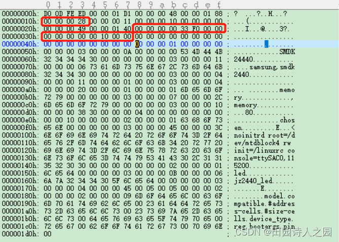
由下面的图可以看出,off_mem_rsvmap 的值为0x00000028,从改地址开始的16Byte的内容是mem rsv的信息,从图中可以看出,mem_rsv的起始地址为: 0x0000000033f00000,大小为0x0000000000100000。设备树的定义:
/memreserve/ 0x33f00000 0x100000;
2.3.2.7 version
version This field shall contain the version of the devicetree data structure. The version is 17 if using the structure as defined in this document. An DTSpec boot program may provide the devicetree of a later version, in which case this field shall contain the version number defined in whichever later document gives the details of that version.- 1
- 2
- 3
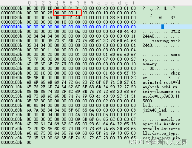
该字段应包含设备树数据结构的版本。如果使用《devicetree-specification-v0.2》定义的结构,则该版本为17。DTSpec引导程序可以提供后续版本的设备,在这种情况下,该字段应包含在提供该版本详细信息的后续文档中定义的版本号。
如下图所示,版本号是0x00000011,即版本号是17。
2.3.2.8 last_comp_version
last_comp_version This field shall contain the lowest version of the devicetree data structure with which the version used is backwards compatible. So, for the structure as defined in this document (version 17), this field shall contain 16 because version 17 is backwards compatible with version 16, but not earlier versions. As per section 5.1, a DTSpec boot program should provide a devicetree in a format which is backwards compatible with version 16, and thus this field shall always contain 16.- 1
- 2
- 3
- 4
- 5
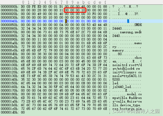
该字段应包含所使用的版本与向后兼容的设备树数据结构的最低版本。因此,对于《devicetree-specification-v0.2》(版本17)中定义的结构,此字段应包含16,因为版本17与版本16向后兼容,但与早期版本不同。DTSpec引导程序应提供向后兼容的设备,因此该字段应始终包含16。
如下图所示,last_comp_version 值为0x00000010,即向后兼容的版本号是16。
2.3.2.9 boot_cpuid_phys
boot_cpuid_phys This field shall contain the physical ID of the system’s boot CPU. It shall be identical to the physical ID given in the reg property of that CPU node within the devicetree.- 1
- 2
该字段应包含系统的引导CPU的物理ID。它应与设备内该CPU节点的注册属性中给出的物理ID相同。
如下图所示,boot_cpuid_phys 的值为0x00000000,表示的是当前处理器的id号为0;size_dt_strings 的大小为0x00000049,表示 strings block的大小为73 Byte,即从0x00000188开始的49Byte的数据都是属于strings block的内容;size_dt_struct 的大小为0x00000140,表示structure block的大小为320 Byte,即从0x00000048地址开始的320 Byte都是structure block的内容。

2.3.2.10 size_dt_strings
size_dt_strings This field shall contain the length in bytes of the strings block section of the devicetree blob.- 1
该字段应包含设备树的字符串块部分的字节长度
2.3.2.11 size_dt_struct
size_dt_struct This field shall contain the length in bytes of the structure block section of the devicetree blob- 1
该字段应包含设备树的结构块部分的字节长度。
2.3.3 Memory Reservation Block
2.3.3.1 Purpose
The memory reservation block provides the client program with a list of areas in physical memory which are reserved; that is, which shall not be used for general memory allocations. It is used to protect vital data structures from being overwritten by the client program. For example, on some systems with an IOMMU, the TCE (translation control entry) tables initialized by a DTSpec boot program would need to be protected in this manner. Likewise, any boot program code or data used during the client program’s runtime would need to be reserved (e.g., RTAS on Open Firmware platforms). DTSpec does not require the boot program to provide any such runtime components, but it does not prohibit implementations from doing so as an extension.- 1
- 2
- 3
- 4
- 5
- 6
内存保留块向客户端程序提供物理内存中保留的区域列表;也就是说,不得用于一般的内存分配。它用于保护重要的数据结构不被客户端程序覆盖。例如,在一些具有IOMMU的系统上,由DTSpec引导程序初始化的TCE(translation control entry)表将需要以这种方式进行保护。同样地,在客户端程序运行期间使用的任何引导程序代码或数据都需要保留(例如,开放固件平台上的RTAS)。DTSpec不要求引导程序提供任何这样的运行时组件,但它并不禁止作为扩展这样实现。
More specifically, a client program shall not access memory in a reserved region unless other information provided by the boot program explicitly indicates that it shall do so. The client program may then access the indicated section of the reserved memory in the indicated manner. Methods by which the boot program can indicate to the client program specific uses for reserved memory may appear in this document, in optional extensions to it, or in platform-specific documentation. The reserved regions supplied by a boot program may, but are not required to, encompass the devicetree blob itself. The client program shall ensure that it does not overwrite this data structure before it is used, whether or not it is in the reserved areas.- 1
- 2
- 3
- 4
- 5
- 6
- 7
更具体地说,除非启动程序提供的其他信息明确指出它应该这样做,否则客户程序不应该访问保留区域的内存。然后客户程序可以以指定的方式访问保留内存的指定部分。引导程序向客户程序指明保留内存的具体用途的方法可以在本文中出现,也可以在本文的可选扩展中出现,或者在特定平台的文档中出现。Boot 程序提供的保留区域可以,但不一定要包括 devicetree blob 本身。客户端程序应确保在使用这个数据结构之前不会覆盖它,无论它是否在保留区域内。
Any memory that is declared in a memory node and is accessed by the boot program or caused to be accessed by the boot program after client entry must be reserved. Examples of this type of access include (e.g., speculative memory reads through a non-guarded virtual page).- 1
- 2
- 3
任何在内存节点中声明的、被 Boot 程序访问的或者在客户端进入后被 Boot 程序访问的内存必须被保留。这种类型的访问的例子包括(例如,通过非守卫的虚拟页进行推测性的内存读取)。
This requirement is necessary because any memory that is not reserved may be accessed by the client program with arbitrary storage attributes.- 1
- 2
这一要求是必要的,因为任何没有被保留的内存都可能被客户程序以任意的存储属性访问。
Any accesses to reserved memory by or caused by the boot program must be done as not Caching Inhibited and Memory Coherence Required (i.e., WIMG = 0bx01x), and additionally for Book III-S implementations as not Write Through Required (i.e., WIMG = 0b001x). Further, if the VLE storage attribute is supported, all accesses to reserved memory must be done as VLE=0.- 1
- 2
- 3
- 4
任何由启动程序引起的对保留内存的访问都必须在不禁止缓存和需要内存一致性的情况下进行(即WIMG = 0bx01x),另外,对于Book III-S的实现,不需要通过写入要求(即,WIMG = 0b001x)。此外,如果支持VLE存储属性,对保留内存的所有访问必须以VLE=0的方式进行。
This requirement is necessary because the client program is permitted to map memory with storage attributes specified as not Write Through Required, not Caching Inhibited, and Memory Coherence Required (i.e., WIMG = 0b001x), and VLE=0 where supported. The client program may use large virtual pages that contain reserved memory. However, the client program may not modify reserved memory, so the boot program may perform accesses to reserved memory as Write Through Required where conflicting values for this storage attribute are architecturally permissible.- 1
- 2
- 3
- 4
- 5
这个要求是必要的,因为客户程序被允许映射内存,其存储属性被指定为不需要通过写入、不禁止缓存和需要内存一致性(即WIMG=0b001x),并且在支持的地方VLE=0。客户端程序可以使用包含保留内存的大型虚拟页。但是,客户程序不能修改保留的内存,所以启动程序可以在这个存储属性的冲突值是架构上允许的情况下,把对保留内存的访问执行为Write Through Required。
2.3.3.2 Format
The memory reservation block consists of a list of pairs of 64-bit big-endian integers, each pair being represented by the following C structure.- 1
- 2
struct fdt_reserve_entry { uint64_t address; /* memory reservation block reserved memory address*/ uint64_t size; /* memory reservation block size */ };- 1
- 2
- 3
- 4
Each pair gives the physical address and size in bytes of a reserved memory region. These given regions shall not overlap each other. The list of reserved blocks shall be terminated with an entry where both address and size are equal to 0. Note that the address and size values are always 64-bit. On 32-bit CPUs the upper 32-bits of the value are ignored. Each uint64_t in the memory reservation block, and thus the memory reservation block as a whole, shall be located at an 8-byte aligned offset from the beginning of the devicetree blob (see section 5.6).- 1
- 2
- 3
- 4
- 5
每一对都给出了保留的内存区域的物理地址和大小(字节)。这些给定的区域不应相互重叠。保留块的列表应以一个地址和大小都等于0的条目结束。 注意,地址和大小值总是64位的。在32位CPU上,该值的前32位被忽略。
内存保留块中的每个uint64_t,以及整个内存保留块,应位于从devicetree blob开始的8字节对齐的偏移处。由下面的图可以看出,off_mem_rsvmap 的值为0x00000028,从改地址开始的16Byte的内容是mem rsv的信息,从图中可以看出,mem_rsv的起始地址为: 0x0000000033f00000,大小为0x0000000000100000。

2.3.4 Structure Block
结构快按照如下的结构去构建结构快
FDT_BEGIN_NODE /* 根节点开始 */ ... FDT_BEGIN_NODE + node_name /* 节点结束开始 */ FDT_PROP + uint32_t len; + uint32_t nameoff; + val /* 属性 1 */ FDT_PROP + uint32_t len; + uint32_t nameoff; + val /* 属性 2 */ FDT_END_NODE /* 节点结束 */ ... FDT_END_NODE /* 根节点结束 */ FDT_END(0x00000009) /* 整个结构结束 */- 1
- 2
- 3
- 4
- 5
- 6
- 7
- 8
- 9
- 10
- 11
The structure block describes the structure and contents of the devicetree itself. It is composed of a sequence of tokens with data, as described below. These are organized into a linear tree structure, as described below. Each token in the structure block, and thus the structure block itself, shall be located at a 4-byte aligned offset from the beginning of the devicetree blob.- 1
- 2
- 3
- 4
结构块描述了devicetree本身的结构和内容。它是由一串带有数据的标记组成的,如下所述。这些数据被组织成一个线性树状结构,如下所述。
结构块中的每个标记,以及结构块本身,应位于从devicetree blob开始的4字节对齐偏移处。2.3.4.1 Lexical structure
The structure block is composed of a sequence of pieces, each beginning with a token, that is, a big-endian 32-bit integer. Some tokens are followed by extra data, the format of which is determined by the token value. All tokens shall be aligned on a 32-bit boundary, which may require padding bytes (with a value of 0x0) to be inserted after the previous token’s data. The five token types are as follows:- 1
- 2
- 3
- 4
结构块由一连串的片断组成,每个片断以一个令牌开始,也就是一个big -endian的32位整数。有些令牌后面是额外的数据,其格式由令牌值决定。所有令牌应在32位边界上对齐,这可能需要在前一个令牌的数据后插入填充字节(值为0x0)。五种令牌类型如下。
- FDT_BEGIN_NODE(0x00000001) 标记一个node的开始
- FDT_END_NODE (0x00000002) 标记一个node的结束
- FDT_PROP (0x00000003) 表示一个属性的开始
- FDT_NOP (0x00000004) 在程序中被忽略
- FDT_END (0x00000009) 标志着结构块的结束
2.3.4.1.1 FDT_BEGIN_NODE (0x00000001)
FDT_BEGIN_NODE (0x00000001) The FDT_BEGIN_NODE token marks the beginning of a node’s representation. It shall be followed by the node’s unit name as extra data. The name is stored as a null-terminated string, and shall include the unit address (see section 2.2.1), if any. The node name is followed by zeroed padding bytes, if necessary for alignment, and then the next token, which may be any token except FDT_END.- 1
- 2
- 3
- 4
FDT_BEGIN_NODE (0x00000001) FDT_BEGIN_NODE令牌标记了一个节点(node)的开始。它后面应该跟着节点的单元名称作为额外的数据。名称存储为以空结尾的字符串,如果有,应包括单元地址(见第2.2.1节)。如果需要对齐,节点名后面是零填充字节,然后是下一个标记,它可能是除FDT_END以外的任何标记。
FDT_BEGIN_NODE + node_name2.3.4.1.2 FDT_END_NODE (0x00000002)
FDT_END_NODE (0x00000002) The FDT_END_NODE token marks the end of a node’s representation. This token has no extra data; so it is followed immediately by the next token, which may be any token except FDT_PROP.- 1
- 2
FDT_END_NODE (0x00000002) FDT_END_NODE令牌标志着一个节点(node)的表示结束。这个标记没有额外的数据;所以它紧接着下一个标记,它可以是任何标记,除了FDT_PROP。
2.3.4.1.3 FDT_PROP (0x00000003)
FDT_PROP (0x00000003) The FDT_PROP token marks the beginning of the representation of one property in the devicetree. It shall be followed by extra data describing the property. This data consists first of the property’s length and name represented as the following C structure:- 1
- 2
FDT_PROP (0x00000003) FDT_PROP令牌标志着devicetree中一个属性的表示开始。它的后面应该是描述该属性的额外数据。这个数据首先包括了属性的长度和名称,以下列C结构表示。
struct { uint32_t len; uint32_t nameoff; }- 1
- 2
- 3
- 4
Both the fields in this structure are 32-bit big-endian integers. • len gives the length of the property’s value in bytes (which may be zero, indicating an empty property, see section 2.2.4.2). • nameoff gives an offset into the strings block (see section 5.5) at which the property’s name is stored as a null-terminated string. After this structure, the property’s value is given as a byte string of length len. This value is followed by zeroed padding bytes (if necessary) to align to the next 32-bit boundary and then the next token, which may be any token except FDT_END.- 1
- 2
- 3
- 4
- 5
- 6
- 7
- 8
这个结构中的两个字段都是32位大端整数。
- Len 给出了属性值的字节长度(可能为零,表示一个空的属性)。
- nameoff 为当前属性名字在字符串块(strings block)的偏移量,其中属性的名称被存储为在字符串块(strings block)中一个以空为结尾的字符串。
在这个结构之后,属性的值以长度为len的字节串形式给出。这个值的后面是归零的填充字节(如果需要),以便与下一个32位边界对齐,然后是下一个标记,可以是除FDT_END之外的任何标记。
所以一个node节点的表示为如下中间部分开始所示的格式:
FDT_BEGIN_NODE /* 根节点开始 */ ... FDT_BEGIN_NODE + node_name /* 节点结束开始 */ FDT_PROP + uint32_t len; + uint32_t nameoff; + val /* 属性 1 */ FDT_PROP + uint32_t len; + uint32_t nameoff; + val /* 属性 2 */ FDT_END_NODE /* 节点结束 */ ... FDT_END_NODE /* 根节点结束 */ FDT_END(0x00000009) /* 整个结构结束 */- 1
- 2
- 3
- 4
- 5
- 6
- 7
- 8
- 9
- 10
- 11
2.3.4.1.4 FDT_NOP (0x00000004)
FDT_NOP (0x00000004) The FDT_NOP token will be ignored by any program parsing the device tree. This token has no extra data; so it is followed immediately by the next token, which can be any valid token. A property or node definition in the tree can be overwritten with FDT_NOP tokens to remove it from the tree without needing to move other sections of the tree’s representation in the devicetree blob.- 1
- 2
- 3
- 4
FDT_NOP (0x00000004) FDT_NOP令牌将被任何解析设备树的程序所忽略。这个标记没有额外的数据;所以它后面紧跟着下一个标记,它可以是任何有效的标记。可以用FDT_NOP标记覆盖树中的属性或节点定义,将其从树中移除,而不需要在devicetree blob中移动设备树的其他部分表示。
2.3.4.1.5 FDT_END (0x00000009)
FDT_END (0x00000009) The FDT_END token marks the end of the structure block. There shall be only one FDT_END token, and it shall be the last token in the structure block. It has no extra data; so the byte immediately after the FDT_END token has offset from the beginning of the structure block equal to the value of the size_dt_struct field in the device tree blob header.- 1
- 2
- 3
- 4
FDT_END (0x00000009) FDT_END令牌标志着结构块的结束。只有一个FDT_END标记,并且它是结构块中的最后一个标记。它没有额外的数据;所以紧随FDT_END标记之后的字节从结构块的开始偏移等于设备树blob头中size_dt_struct字段的值。
2.3.4.2 Tree structure
The devicetree structure is represented as a linear tree: the representation of each node begins with an FDT_BEGIN_NODE token and ends with an FDT_END_NODE token. The node’s properties and subnodes (if any) are represented before the FDT_END_NODE, so that the FDT_BEGIN_NODE and FDT_END_NODE tokens for those subnodes are nested within those of the parent. The structure block as a whole consists of the root node’s representation (which contains the representations for all other nodes), followed by an FDT_END token to mark the end of the structure block as a whole. More precisely, each node’s representation consists of the following components: • (optionally) any number of FDT_NOP tokens • FDT_BEGIN_NODE token – The node’s name as a null-terminated string – [zeroed padding bytes to align to a 4-byte boundary] • For each property of the node: – (optionally) any number of FDT_NOP tokens – FDT_PROP token * property information as given in section 5.4.1 * [zeroed padding bytes to align to a 4-byte boundary] • Representations of all child nodes in this format • (optionally) any number of FDT_NOP tokens • FDT_END_NODE token Note that this process requires that all property definitions for a particular node precede any subnode definitions for that node. Although the structure would not be ambiguous if properties and subnodes were intermingled, the code needed to process a flat tree is simplified by this requirement.- 1
- 2
- 3
- 4
- 5
- 6
- 7
- 8
- 9
- 10
- 11
- 12
- 13
- 14
- 15
- 16
- 17
- 18
- 19
- 20
- 21
- 22
2.3.4.3 结构快示例
结构快按照如下的结构去构建结构快
FDT_BEGIN_NODE /* 根节点开始 */ ... FDT_BEGIN_NODE + node_name /* 节点结束开始 */ FDT_PROP + uint32_t len; + uint32_t nameoff; + val /* 属性 1 */ FDT_PROP + uint32_t len; + uint32_t nameoff; + val /* 属性 2 */ FDT_END_NODE /* 节点结束 */ ... FDT_END_NODE /* 根节点结束 */ FDT_END(0x00000009) /* 整个结构结束 */- 1
- 2
- 3
- 4
- 5
- 6
- 7
- 8
- 9
- 10
- 11
2.3.4.4 结构快样例
2.3.4.4.1 dtb文件的格式
如下图所示:
地址0x00000048开始分析,按照地址:内容:含义的形式去分析
0x00000048:0x00000001:FDT_BEGIN_NODE表述节点开始(此处为根节点)
0x00000050:0x00000003:FDT_PROP 表述属性的开始
0x00000054:0x0000000A:uint32_t len 表示属性值的字节长度为10 Byte
0x00000058:0x00000000:uint32_t nameoff 表述属性名字在strings block的偏移地址为0,
0x00000188:model:表示属性的名字为model
0x0000005c:SMDK24440:表述属性的val为SMDK244400x00000068:0x00000003:FDT_PROP 表述属性的开始
0x0000006C:0x00000011:uint32_t len 表示属性值的字节长度为17 Byte
0x00000058:0x00000006:uint32_t nameoff 表述属性名字在strings block的偏移地址为6,
0x0000018e:compatible:表示属性的名字为compatible
0x0000005c:samsung,smdk2440:表述属性的val为samsung,smdk24400x00000180:0x00000002:FDT_END_NODE表述节点结束(此处为根节点)
0x00000184:0x00000009:FDT_END 表示structure block的结束
2.3.4.4.2 设备树的定义
设备树的定义
/dts-v1/; /memreserve/ 0x33f00000 0x100000; / { model = "SMDK24440"; compatible = "samsung,smdk2440"; #address-cells = <1>; #size-cells = <1>; memory { /* /memory */ device_type = "memory"; reg = <0x30000000 0x4000000 0 4096>; }; /* cpus { cpu { compatible = "arm,arm926ej-s"; }; }; */ chosen { bootargs = "noinitrd root=/dev/mtdblock4 rw init=/linuxrc console=ttySAC0,115200"; }; led { compatible = "jz2440_led"; pin = <S3C2410_GPF(5)>; }; };- 1
- 2
- 3
- 4
- 5
- 6
- 7
- 8
- 9
- 10
- 11
- 12
- 13
- 14
- 15
- 16
- 17
- 18
- 19
- 20
- 21
- 22
- 23
- 24
- 25
- 26
- 27
- 28
- 29
- 30
- 31
- 32
- 33
- 34
2.3.5 Strings Block
The strings block contains strings representing all the property names used in the tree. These null terminated strings are simply concatenated together in this section, and referred to from the structure block by an offset into the strings block. The strings block has no alignment constraints and may appear at any offset from the beginning of the devicetree blob.- 1
- 2
- 3
字符串块包含设备树中使用的所有属性名称的字符串。这些空结尾的字符串在本节中被简单地串联起来,并通过字符串块的偏移量从结构块中引用。字符串块没有对齐限制,可以出现在从devicetree blob开始的任何偏移处。
如下图所示,每个属性名字都以0x00结束,然后开始另一个属性名字

- 分配,设置,注册file_operations结构体(
-
相关阅读:
【无标题】
FreeRtos进阶——中断的内部逻辑
java框架-Springboot3-场景整合
MYSQL round()函数
基于SSM和Web实现的农作物生长监控系统设计与实现
Mysql修改密码
Windows11安装Vim编辑器配置指南
Jmeter面试题
三、《任务列表案例》前端程序搭建和运行
shell程序中常见的正规表达式
- 原文地址:https://blog.csdn.net/u014100559/article/details/124950936