-
从0手写两轮差速机器人urdf模型
前言
最近为找到与自己课题应用场景相适应的机器人结构,对机器人建模方面的内容进行了了解和学习,计划是通过solidworks自己设计一个机器人模型,然后将其导入到gazebo仿真环境下进行三维世界的仿真。先实现最简单的创建两轮差速机器人urdf模型
一、基本理论
URDF(Unified Robot Description Format)即统一机器人描述格式,是ROS中一个非常重要的机器人模型描述格式,包含link和joint自身及相关属性的描述信息,可以通过手写URDF文件中XML格式代码来构建自己的机器人模型。
(1)描述机器人某个刚体部分的外观和物理属性
(2)描述连杆尺寸(size)、颜色(color)、形状(shape)、惯性矩阵(inertial matrix)、碰撞参数(collision properties)等
(3)每个link会成为一个坐标系
(1)描述两个link之间的关系,分为六种类型
(2)包括关节运动的位置和速度限制
(3)描述机器人关节的运动学和动力学属性
(1)完整机器人模型的最顶层标签
(2)和标签都必须包含在标签内
(3)一个完整的机器人模型,由;一系列和组成二、实现步骤
1.创建一个机器人建模功能包
(1)创建工作空间:
mkdir -p ~/test_ws/src

(2)在新创建的test工作空间的src文件夹中创建mbot_description建模功能包,即在src文件夹下,打开终端,输入:
catkin_create_pkg mbot_description urdf xacro- 1
 (3)在mbot_description功能包下床价以下4个文件夹:
urdf: 存放机器人模型的URDF或xacro文件
meshes: 放置URDF中饮用的模型渲染文件
launch: 保存相关启动文件
config: 保存rviz的配置文件

2.使用圆柱体创建一个车体模型
(1)进入mbot_description功能包中的urdf文件夹,打开终端,输入:
touch mbot.urdf- 1

(2)手写link和node对机器人模型进行描述
base_link<?xml version="1.0" ?> <!-- xml版本号为1.0 --> <robot name="mbot"> <!--设置机器人的名字 --> <link name="base_link"> <!--设置link名字:base_link为底盘 --> <visual> <!--visual为可视化部分 --> <origin xyz=" 0 0 0" rpy="0 0 0" /> <!--机器人的初始位置 --> <geometry> <cylinder length="0.16" radius="0.20"/> <!--机器人主体设为圆柱体,高度0.16m,半径0.20m --> </geometry> <material name="Yellow"/> <!--设置机器人底座的外观颜色 --> </visual> </link> </robot>- 1
- 2
- 3
- 4
- 5
- 6
- 7
- 8
- 9
- 10
- 11
- 12
- 13
- 14
- 15
颜色 material<material name="Black"> <color rgba="0 0 0 1"/> </material> <material name="White"> <color rgba="1 1 1 0.95"/> </material> <material name="Blue"> <color rgba="0 0 1 1"/> </material> <material name="Yellow"> <color rgba="1 0.4 0 1"/> </material>- 1
- 2
- 3
- 4
- 5
- 6
- 7
- 8
- 9
- 10
- 11
- 12
(3)写launch文件调用rviz进行显示
进入工作空间的launch文件夹中,打开终端,输入:
touch display_mbot_urdf.launch- 1

在launch文件中输入以下指令:<launch> <!-- 设置机器人模型路径参数 --> <param name="robot_description" textfile="$(find mbot_description)/urdf/mbot.urdf" /> <!-- 运行joint_state_publisher节点,发布机器人的关节状态 --> <node name="joint_state_publisher_gui" pkg="joint_state_publisher_gui" type="joint_state_publisher_gui" /> <!-- 运行robot_state_publisher节点,发布tf --> <node name="robot_state_publisher" pkg="robot_state_publisher" type="robot_state_publisher" /> <!-- 运行rviz可视化界面 --> <node name="rviz" pkg="rviz" type="rviz" args="-d $(find mbot_description)/config/mbot_urdf.rviz" required="true" /> </launch>- 1
- 2
- 3
- 4
- 5
- 6
- 7
- 8
- 9
- 10
- 11
- 12
- 13
运行launch文件前在工作空间下进行编译,在终端输入
catkin_make,确保环境变量能够找到功能包。
颜色 material<material name="Black"> <color rgba="0 0 0 1"/> </material> <material name="White"> <color rgba="1 1 1 0.95"/> </material> <material name="Blue"> <color rgba="0 0 1 1"/> </material> <material name="Yellow"> <color rgba="1 0.4 0 1"/> </material> ```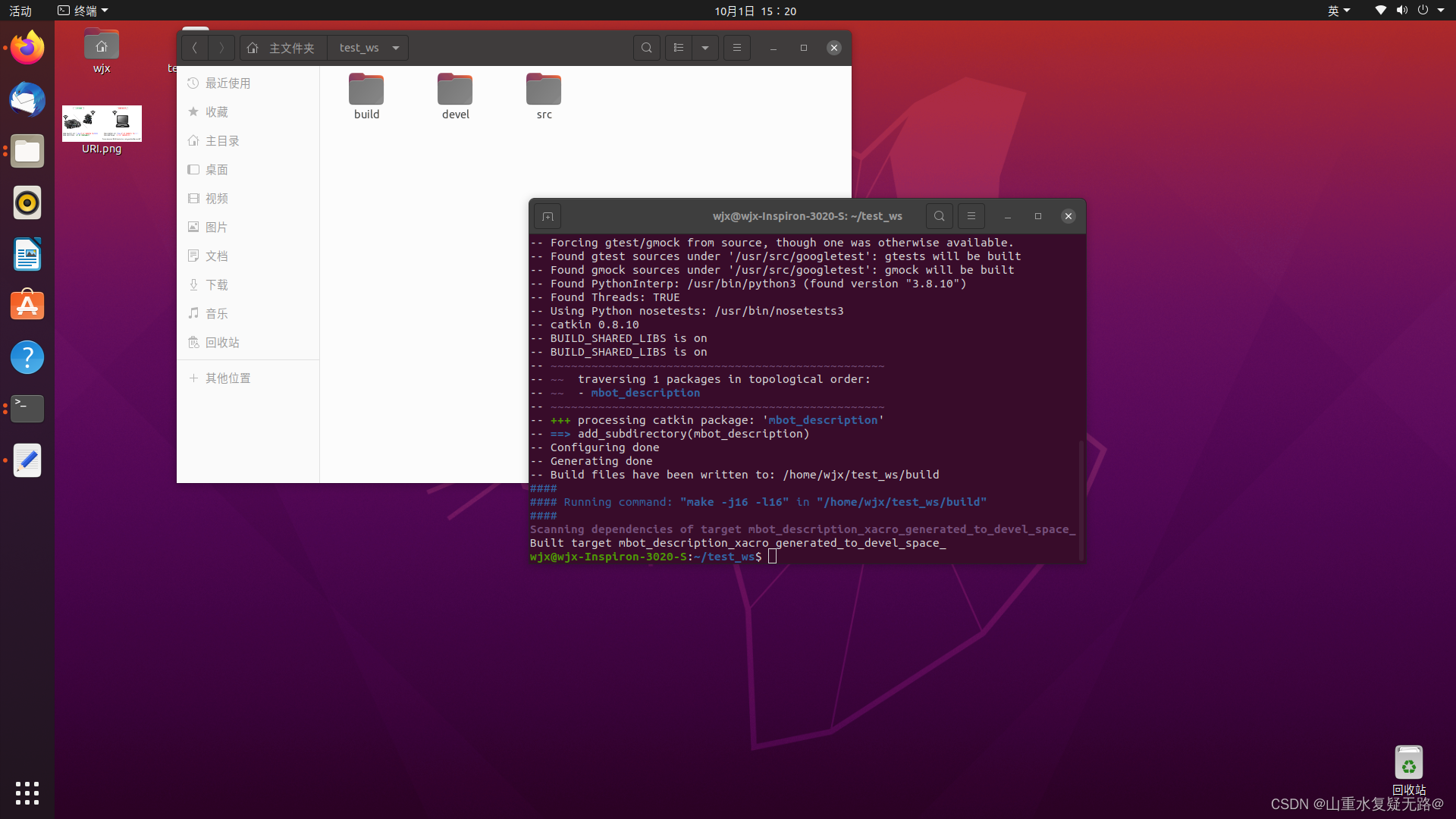 启动mbot_description.launch文件,打开终端输入: ```cpp roslaunch mbot_description display_mbot_urdf.launch- 1
- 2
- 3
- 4
- 5
- 6
- 7
- 8
- 9
- 10
- 11
- 12
- 13
- 14
- 15
- 16
- 17
出现报错:
 在终端输入:
echo 'source ~/test_ws/devel/setup.bash' >> ~/.bashrc source .bashrc- 1
- 2

再次启动mbot_description.launch文件,可成功启动
通过Add来添加一个机器人模型:
报错No transform from [base_link] to [map],将Fixed Frame改为base_link,可成功显示机器人底盘,如图:mbot_description.launch

为避免下次启动还要重新添加一遍,保存一下
mbot_description.launch

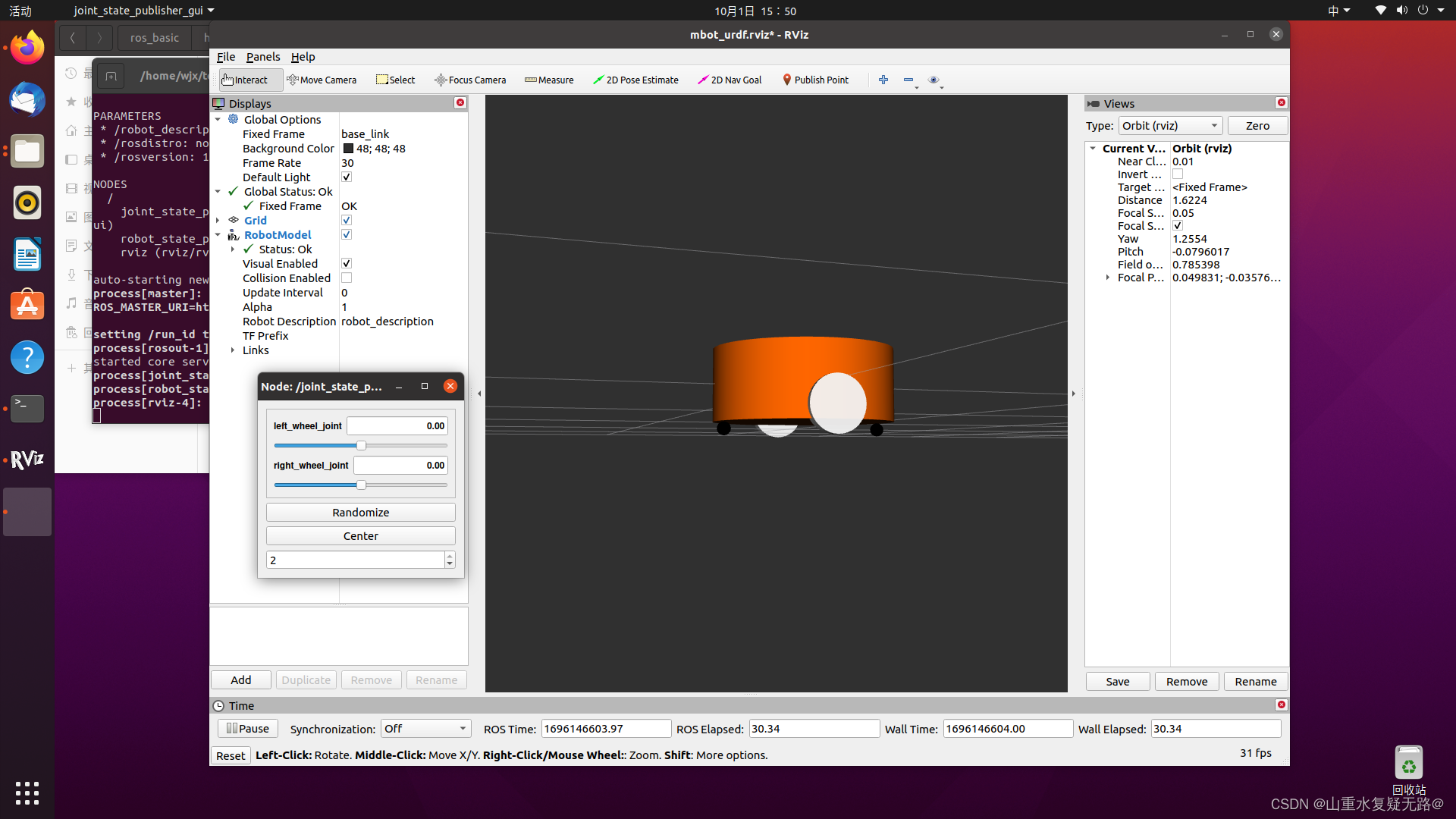
2.同理创建机器人其它构件
左轮 left_wheel_link<link name="left_wheel_link"> <visual> <origin xyz="0 0 0" rpy="1.5707 0 0" /> <geometry> <cylinder radius="0.06" length = "0.025"/> </geometry> <material name="White"/> </visual> </link> <joint name="left_wheel_joint" type="continuous"> <origin xyz="0 0.19 -0.05" rpy="0 0 0"/> <parent link="base_link"/> <child link="left_wheel_link"/> <axis xyz="0 1 0"/> </joint>- 1
- 2
- 3
- 4
- 5
- 6
- 7
- 8
- 9
- 10
- 11
- 12
- 13
- 14
- 15
- 16
右轮 right_wheel_link<link name="right_wheel_link"> <visual> <origin xyz="0 0 0" rpy="1.5707 0 0" /> <geometry> <cylinder radius="0.06" length = "0.025"/> </geometry> <material name="White"/> </visual> </link> <joint name="right_wheel_joint" type="continuous"> <origin xyz="0 -launch0.19 -0.05" rpy="0 0 0"/> <parent link="base_link"/> <child link="right_wheel_link"/> <axis xyz="0 1 0"/> </joint>- 1
- 2
- 3
- 4
- 5
- 6
- 7
- 8
- 9
- 10
- 11
- 12
- 13
- 14
- 15
- 16
前后支撑轮 CASTER<link name="front_caster_link"> <visual> <origin xyz="0 0 0" rpy="0 0 0"/> <geometry> <sphere radius="0.015" /> </geometry> <material name="Black"/> </visual> </link> <joint name="front_caster_joint" type="fixed"> <origin xyz="0.18 0 -0.095" rpy="0 0 0"/> <parent link="base_link"/> <child link="front_caster_link"/> </joint> <link name="back_caster_link"> <visual> <origin xyz="0 0 0" rpy="0 0 0"/> <geometry> <sphere radius="0.015" /> </geometry> <material name="Black"/> </visual> </link> <joint name="back_caster_joint" type="fixed"> <origin xyz="-0.18 0 -0.095" rpy="0 0 0"/> <parent link="base_link"/> <child link="back_caster_link"/> </joint>- 1
- 2
- 3
- 4
- 5
- 6
- 7
- 8
- 9
- 10
- 11
- 12
- 13
- 14
- 15
- 16
- 17
- 18
- 19
- 20
- 21
- 22
- 23
- 24
- 25
- 26
- 27
- 28
- 29
- 30
- 31
创建成功,运行mbot_description.launch文件,如图:
3.机器人模型添加传感器
(1)添加激光雷达
保存上面构建的机器人呢小车基本模型,在urdf文件夹下复制mbot.urdf文件,重新起名为mbot_with_laser.urdf

mbot_with_laser.urdf整个机器人底盘都是不需要更改的,唯一需要添加的就是激光雷达传感器的模型。激光雷达 laser<link name="laser_link"> <visual> <origin xyz=" 0 0 0 " rpy="0 0 0" /> <geometry> <cylinder length="0.05" radius="0.05"/> </geometry> <material name="Black"/> </visual> </link> <joint name="laser_joint" type="fixed"> <origin xyz="0 0 0.105" rpy="0 0 0"/> <parent link="base_link"/> <child link="laser_link"/> </joint>- 1
- 2
- 3
- 4
- 5
- 6
- 7
- 8
- 9
- 10
- 11
- 12
- 13
- 14
- 15
添加启动的display_mbot_with_laser_urdf.launch文件
<launch> <!-- 设置机器人模型路径参数 --> <param name="robot_description" textfile="$(find mbot_description)/urdf/mbot_with_laser.urdf" /> <!-- 运行joint_state_publisher节点,发布机器人的关节状态 --> <node name="joint_state_publisher_gui" pkg="joint_state_publisher_gui" type="joint_state_publisher_gui" /> <!-- 运行robot_state_publisher节点,发布tf --> <node name="robot_state_publisher" pkg="robot_state_publisher" type="robot_state_publisher" /> <!-- 运行rviz可视化界面 --> <node name="rviz" pkg="rviz" type="rviz" args="-d $(find mbot_description)/config/mbot_urdf.rviz" required="true" /> </launch>- 1
- 2
- 3
- 4
- 5
- 6
- 7
- 8
- 9
- 10
- 11
- 12
- 13
启动launch文件如下图:

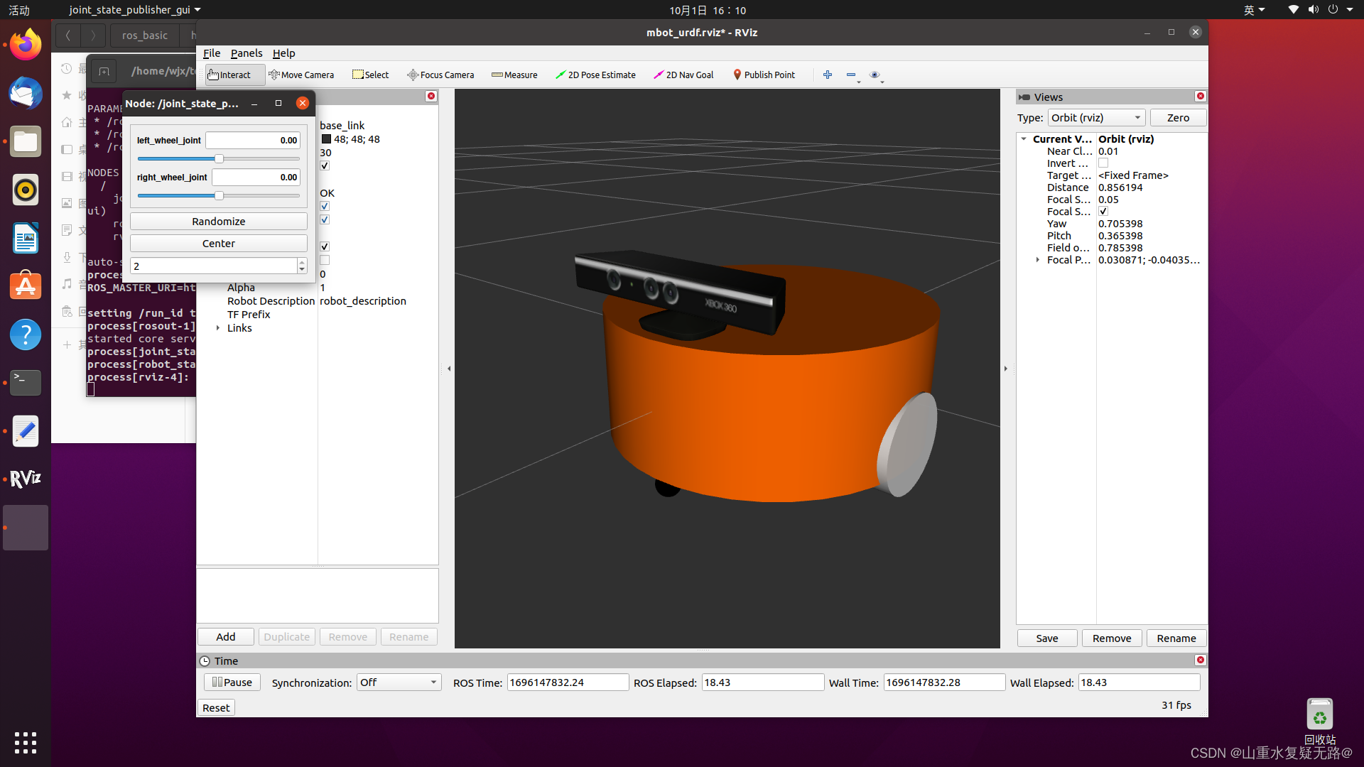
(2)添加kinect相机
同理复制mbot.urdf文件,重命名display_mbot_with_kinect_urdf.launch

深度相机 kinect<link name="kinect_link"> <visual> <origin xyz="0 0 0" rpy="0 0 1.5708"/> <geometry> <mesh filename="package://mbot_description/meshes/kinect.dae" /> </geometry> </visual> </link> <joint name="kinect_joint" type="fixed"> <origin xyz="0.15 0 0.11" rpy="0 0 0"/> <parent link="base_link"/> <child link="kinect_link"/> </joint>- 1
- 2
- 3
- 4
- 5
- 6
- 7
- 8
- 9
- 10
- 11
- 12
- 13
- 14
添加启动的display_mbot_with_kinect_urdf.launch文件
<launch> <!-- 设置机器人模型路径参数 --> <param name="robot_description" textfile="$(find mbot_description)/urdf/mbot_with_kinect.urdf" /> <!-- 运行joint_state_publisher节点,发布机器人的关节状态 --> <node name="joint_state_publisher_gui" pkg="joint_state_publisher_gui" type="joint_state_publisher_gui" /> <!-- 运行robot_state_publisher节点,发布tf --> <node name="robot_state_publisher" pkg="robot_state_publisher" type="robot_state_publisher" /> <!-- 运行rviz可视化界面 --> <node name="rviz" pkg="rviz" type="rviz" args="-d $(find mbot_description)/config/mbot_urdf.rviz" required="true" /> </launch>- 1
- 2
- 3
- 4
- 5
- 6
- 7
- 8
- 9
- 10
- 11
- 12
- 13
启动launch文件如下图:
-
相关阅读:
bootz启动 Linux内核过程总结
看过来——用Python探索《红楼梦》的人物关系
人体神经系统分类图解,人体神经系统分类图片
Lesson17——NumPy 统计函数
HTML轮播图 页脚问题 急!
使用 Vue3 + ts 开发一个ProTable
CarSim仿真快速入门(十九)—CarSim2021中ESC控制demo
JavaScript基础语法(流程控制语句)
Odoo | Config | Odoo版本基础需求
flutter项目常用组件
- 原文地址:https://blog.csdn.net/qq_45252077/article/details/133464378

- 最新文章
-
沪漂五周年了:我越来越迷茫了
Agentic Skill Routing 实战:别再把所有 Skill 塞进 AI Agent 上下文
MySQL-Seconds_behind_master的精度误差
[MAF预定义ChatClient中间件-03]CachingChatClient——利用缓存省钱省时间
AI的至暗历史:从万众期待到被政府撤资,AI的两次死亡徘徊
Agent OS :五种驯服不确定性的范式
PortSwigger SQL注入LAB11
数据库即时编译JIT
[Begin]AI Learn Data Day 0
深度学习进阶(二十七)现代 LLM 的核心架构设计其二:SwiGLU