-
嵌入式Linux驱动开发(I2C专题)(七)
使用GPIO操作I2C设备_IMX6ULL
参考资料:
- Linux文档
Linux-5.4\Documentation\devicetree\bindings\i2c\i2c-gpio.yamlLinux-4.9.88\Documentation\devicetree\bindings\i2c\i2c-gpio.txt
- Linux驱动源码
Linux-5.4\drivers\i2c\busses\i2c-gpio.cLinux-4.9.88\drivers\i2c\busses\i2c-gpio.c
1. 硬件连接
- IMX6ULL:把I2C模块接到GPIO

2. 根据原理图编写设备树
2.1 原理图

2.2 编写设备树
i2c_gpio_100ask { compatible = "i2c-gpio"; gpios = <&gpio4 20 0 /* sda */ &gpio4 21 0 /* scl */ >; i2c-gpio,delay-us = <5>; /* ~100 kHz */ #address-cells = <1>; #size-cells = <0>; };- 1
- 2
- 3
- 4
- 5
- 6
- 7
- 8
- 9
把上述代码,放入
arch/arm/boot/dts/100ask_imx6ull-14x14.dts的根节点下面。3. 确认内核已经配置了I2C-GPIO
查看内核目录下的
.config,如果未设置CONFIG_I2C_GPIO,上机实验时需要配置内核、编译I2C-GPIO驱动。4. 上机实验
4.1 设置工具链
-
IMX6ULL
export ARCH=arm export CROSS_COMPILE=arm-linux-gnueabihf- export PATH=$PATH:/home/book/100ask_imx6ull-sdk/ToolChain/gcc-linaro-6.2.1-2016.11-x86_64_arm-linux-gnueabihf/bin- 1
- 2
- 3
4.2 编译、替换设备树
-
编译设备树:
在Ubuntu的IMX6ULL内核目录下执行如下命令,
得到设备树文件:arch/arm/boot/dts/100ask_imx6ull-14x14.dtbmake dtbs- 1
-
复制到NFS目录:
$ cp arch/arm/boot/dts/100ask_imx6ull-14x14.dtb ~/nfs_rootfs/- 1
-
开发板上挂载NFS文件系统
-
vmware使用NAT(假设windowsIP为192.168.1.100)
[root@100ask:~]# mount -t nfs -o nolock,vers=3,port=2049,mountport=9999 192.168.1.100:/home/book/nfs_rootfs /mnt- 1
- 2
-
vmware使用桥接,或者不使用vmware而是直接使用服务器:假设Ubuntu IP为192.168.1.137
[root@100ask:~]# mount -t nfs -o nolock,vers=3 192.168.1.137:/home/book/nfs_rootfs /mnt- 1
-
-
更新设备树
[root@100ask:~]# cp /mnt/100ask_imx6ull-14x14.dtb /boot [root@100ask:~]# sync- 1
- 2
-
重启开发板
4.3 编译I2C-GPIO驱动
1. 配置内核
在IMX6ULL内核源码目录下执行
make menuconfig命令,如下配置内核:Device Drivers ---> I2C support ---> I2C Hardware Bus support ---> <M> GPIO-based bitbanging I2C // 输入M,编译为模块- 1
- 2
- 3
- 4
2. 编译模块
设置工具链后,在内核目录下执行:
make modules // 得到 drivers/i2c/busses/i2c-gpio.ko- 1
5. 测试
在开发板上执行:
[root@100ask:~]# i2cdetect -l // 加载i2c-gpio.ko前只看到2条I2C BUS i2c-1 i2c 21a4000.i2c I2C adapter i2c-0 i2c 21a0000.i2c I2C adapter [root@100ask:~]# [root@100ask:~]# insmod /mnt/i2c-gpio.ko [ 45.067602] i2c-gpio i2c_gpio_100ask: using pins 116 (SDA) and 117 (SCL) [root@100ask:~]# i2cdetect -l // 加载i2c-gpio.ko后看到3条I2C BUS i2c-1 i2c 21a4000.i2c I2C adapter i2c-4 i2c i2c_gpio_100ask I2C adapter i2c-0 i2c 21a0000.i2c I2C adapter [root@100ask:~]# [root@100ask:~]# i2cdetect -y 4 // 检测到0x50的设备 0 1 2 3 4 5 6 7 8 9 a b c d e f 00: -- -- -- -- -- -- -- -- -- -- -- -- -- 10: -- -- -- -- -- -- -- -- -- -- -- -- -- -- -- -- 20: -- -- -- -- -- -- -- -- -- -- -- -- -- -- -- -- 30: -- -- -- -- -- -- -- -- -- -- -- -- -- -- -- -- 40: -- -- -- -- -- -- -- -- -- -- -- -- -- -- -- -- 50: 50 -- -- -- -- -- -- -- -- -- -- -- -- -- -- -- 60: -- -- -- -- -- -- -- -- -- -- -- -- -- -- -- -- 70: -- -- -- -- -- -- -- -- [root@100ask:~]# [root@100ask:~]# i2cset -f -y 4 0x50 0 0x55 // 往0地址写入0x55 [root@100ask:~]# i2cget -f -y 4 0x50 0 // 读0地址 0x55- 1
- 2
- 3
- 4
- 5
- 6
- 7
- 8
- 9
- 10
- 11
- 12
- 13
- 14
- 15
- 16
- 17
- 18
- 19
- 20
- 21
- 22
- 23
- 24
- 25
具体芯片的I2C_Adapter驱动分析
参考资料:
- Linux内核真正的I2C控制器驱动程序
- IMX6ULL:
Linux-4.9.88\drivers\i2c\busses\i2c-imx.c - STM32MP157:
Linux-5.4\drivers\i2c\busses\i2c-stm32f7.c
- IMX6ULL:
1. I2C控制器内部结构
1.1 通用的简化结构

1.2 IMX6ULL的I2C控制器内部结构

1.3 STM32MP157的I2C控制器内部结构

2. I2C控制器操作方法
- 使能时钟、设置时钟
- 发送数据:
- 把数据写入tx_register,等待中断发生
- 中断发生后,判断状态:是否发生错误、是否得到回应信号(ACK)
- 把下一个数据写入tx_register,等待中断:如此循环
- 接收数据:
- 设置controller_register,进入接收模式,启动接收,等待中断发生
- 中断发生后,判断状态,读取rx_register得到数据
- 如此循环
3. 分析代码
3.1 设备树
-
IMX6ULL:
arch/arm/boot/dts/imx6ull.dtsii2c1: i2c@021a0000 { #address-cells = <1>; #size-cells = <0>; compatible = "fsl,imx6ul-i2c", "fsl,imx21-i2c"; reg = <0x021a0000 0x4000>; interrupts = <GIC_SPI 36 IRQ_TYPE_LEVEL_HIGH>; clocks = <&clks IMX6UL_CLK_I2C1>; status = "disabled"; // 在100ask_imx6ull-14x14.dts把它改为了"okay" };- 1
- 2
- 3
- 4
- 5
- 6
- 7
- 8
- 9
-
STM32MP157:
arch/arm/boot/dts/stm32mp151.dtsii2c1: i2c@40012000 { compatible = "st,stm32mp15-i2c"; reg = <0x40012000 0x400>; interrupt-names = "event", "error"; interrupts-extended = <&exti 21 IRQ_TYPE_LEVEL_HIGH>, <&intc GIC_SPI 32 IRQ_TYPE_LEVEL_HIGH>; clocks = <&rcc I2C1_K>; resets = <&rcc I2C1_R>; #address-cells = <1>; #size-cells = <0>; dmas = <&dmamux1 33 0x400 0x80000001>, <&dmamux1 34 0x400 0x80000001>; dma-names = "rx", "tx"; power-domains = <&pd_core>; st,syscfg-fmp = <&syscfg 0x4 0x1>; wakeup-source; status = "disabled"; // 在stm32mp15xx-100ask.dtsi把它改为了"okay" };- 1
- 2
- 3
- 4
- 5
- 6
- 7
- 8
- 9
- 10
- 11
- 12
- 13
- 14
- 15
- 16
- 17
- 18
3.2 驱动程序分析
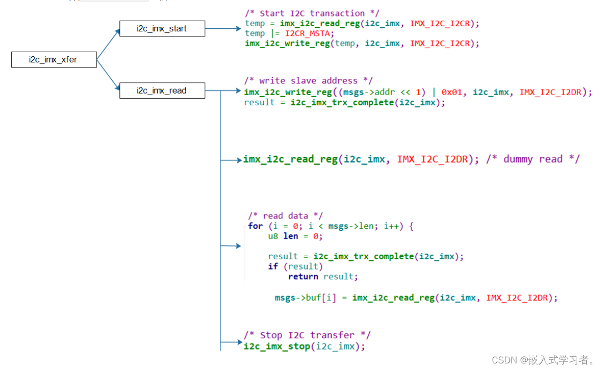
读I2C数据时,要先发出设备地址,这是写操作,然后再发起读操作,涉及写、读操作。所以以读I2C数据为例讲解核心代码。
-
IMX6ULL:函数
i2c_imx_xfer分析:
-
STM32MP157:函数
stm32f7_i2c_xfer分析
这函数完全有驱动程序来驱动:启动传输后,就等待;在中断服务程序里传输下一个数据,知道传输完毕。- 启动传输

- 通过中断进行后续传输

- 启动传输
- Linux文档
-
相关阅读:
【服务器学习】scheduler协程调度模块
最新版:RadSystems Studio:Crack
贝叶斯推理三种方法:MCMC 、HMC和SBI
C语言-文件操作(最全)(二十一)
案例推荐|助力智慧城市,Pulsar Functions 的边缘物联网场景实践
Spring Boot Actuator 管理日志
git操作学习记录,简单易上手
【机器学习算法】聚类算法-3 K均值聚类法,PAM法,神经网络聚类法SOM
springboot集成swagger3.0
原生js值之数据类型详解
- 原文地址:https://blog.csdn.net/afddasfa/article/details/132981137
