-
FPGA原理与结构(13)——FIFO IP核的使用与测试
系列文章目录:FPGA原理与结构(0)——目录与传送门
一、前言
本文介绍FIFO Generator v13.2 IP核的具体使用与例化,在学习一个IP核的使用之前,首先需要对于IP核的具体参数和原理有一个基本的了解,具体可以参考:
二、FIFO IP核定制
1、FIFO IP核
step1 打开vivado工程,点击左侧栏中的IP Catalog

step2 在搜索栏搜索FIFO,找到FIFO Generator核

2、IP核定制
step3 Basic 界面定制
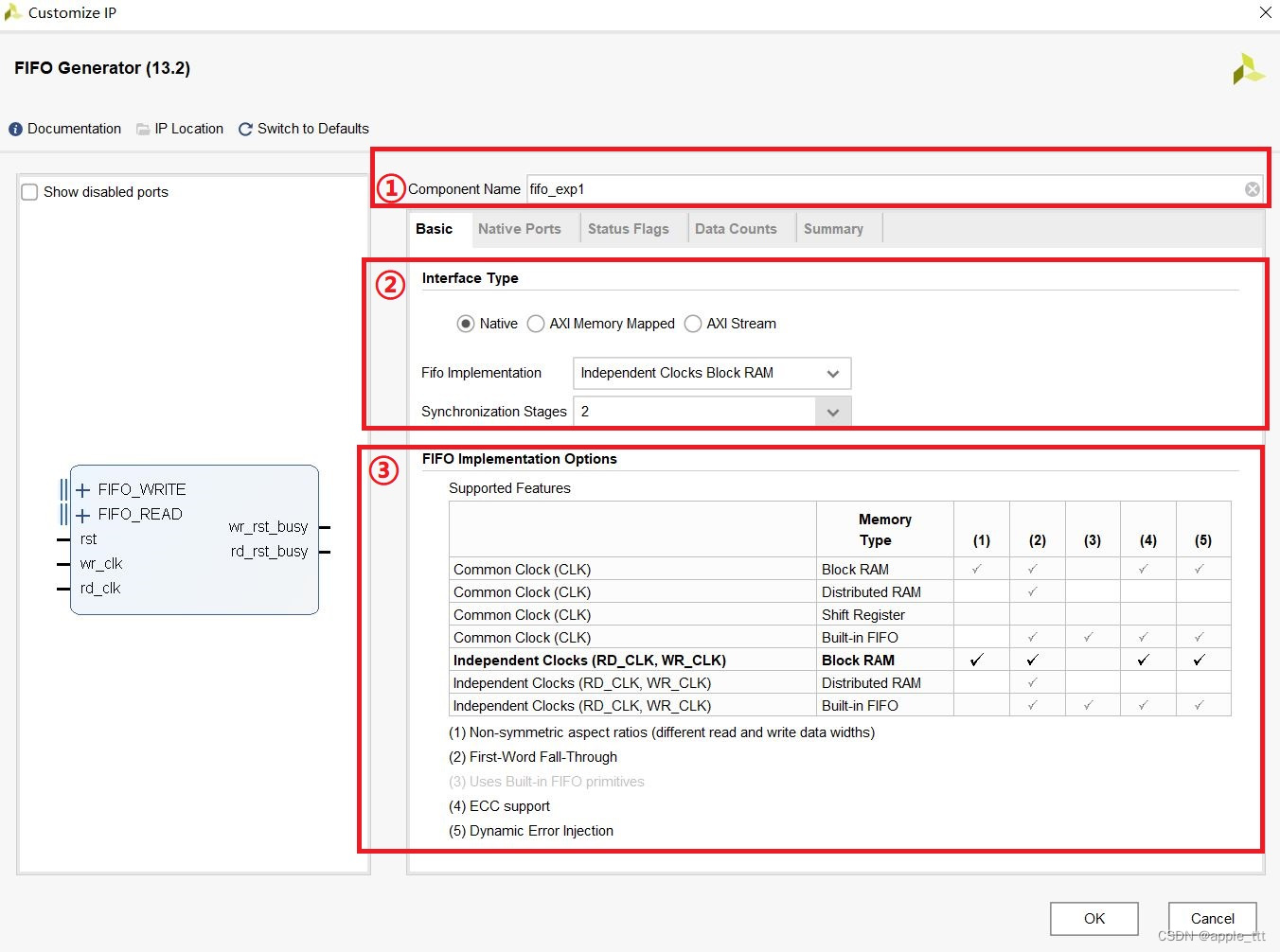
①Component Name :自定义FIFO的名称
②Interface Type :接口类型,我们知道FIFO可以支持Native接口和AXI接口,其中AXI接口包括AXI3,AXI4,AXI Stream类型,这里我们选择Native。
Fifo Implementation :用于选择我们想要实现的是同步 FIFO 还是异步 FIFO 以及使用哪种资源实现 FIFO,这里我们选择“Independent Clocks Block RAM”,即使用块 RAM 来实现的异步 FIFO。Synchronization Stages :同步级数,这里保持默认为2,如果有更高的频率要求,可以提升。③FIFO Implementation Options :不同资源类型实现FIFO所能支持的功能列表,大家根据表格自行观察连接即可。
step4 Native Ports 界面设计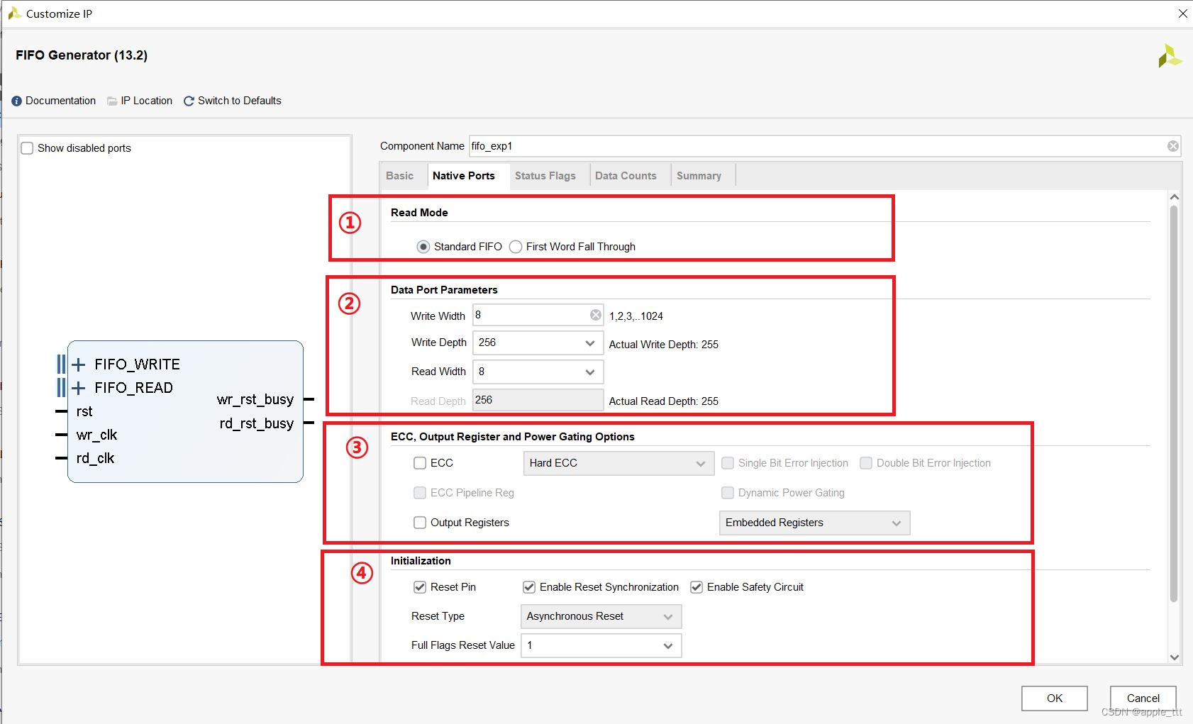 ①Read Mode :用于设置读 FIFO 时的读模式,可选的有标准模式和前显模式,一般没有特殊需求的前提下,我们推荐标准模式。这里我们选择默认的“Standard FIFO”。②Data Port Parameters :用于设置读写端口的数据总线的宽度以及 FIFO 的深度,写宽度“Write Width”我们设置为 8 位,写深度“Write Depth”我们设置为 256,注意此时 FIFO IP 核所能实现的实际深度却是 255;虽然读宽度“Read Width”能够设置成和 写宽度不一样的位宽,且此时读深度“Read Depth”会根据上面三个参数被动地自动设置成相应的值;但是我们还是将读宽度“Read Width”设置成和写宽度“Write Width”一样的位宽,这也是在实际应用中最常用的情况。③ ECC模式:在本次的FIFO测试中不使用④ Initiazation :用于设置FIFO的复位等相关内容,默认同步复位,安全复位,full在复位时保持高电平有效。
step5 Status Flags 界面定制
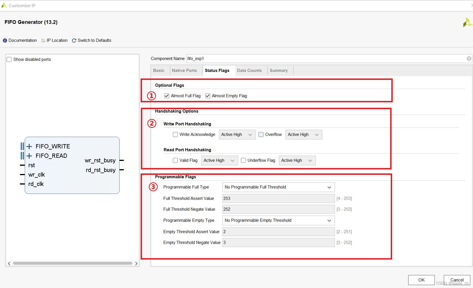 “Status Flags”界面,这个界面用于设置用户自定义接口或者用于设定专用的输入口。① Optional Flags : 可选信号,在这里可以勾选将空和将满信号,这里我们都勾上。② Handshaking Options :握手信号,这里我们使用不到,就不勾选了。③ Programmable Flags : 可编程阈值,这里我们也不做选择。
step6 Data Counts
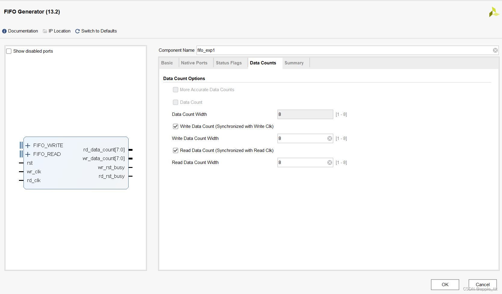 Data Counts界面用于设置 FIFO 内数据计数的输出信号,此信号表示当前在 FIFO 内存在多少个有效数据。为了更加方便地观察读/写过程,这里我们把读/写端口的数据计数都打开,且计数值总线的位宽设置为满位宽,即 8 位。
step7 Summary
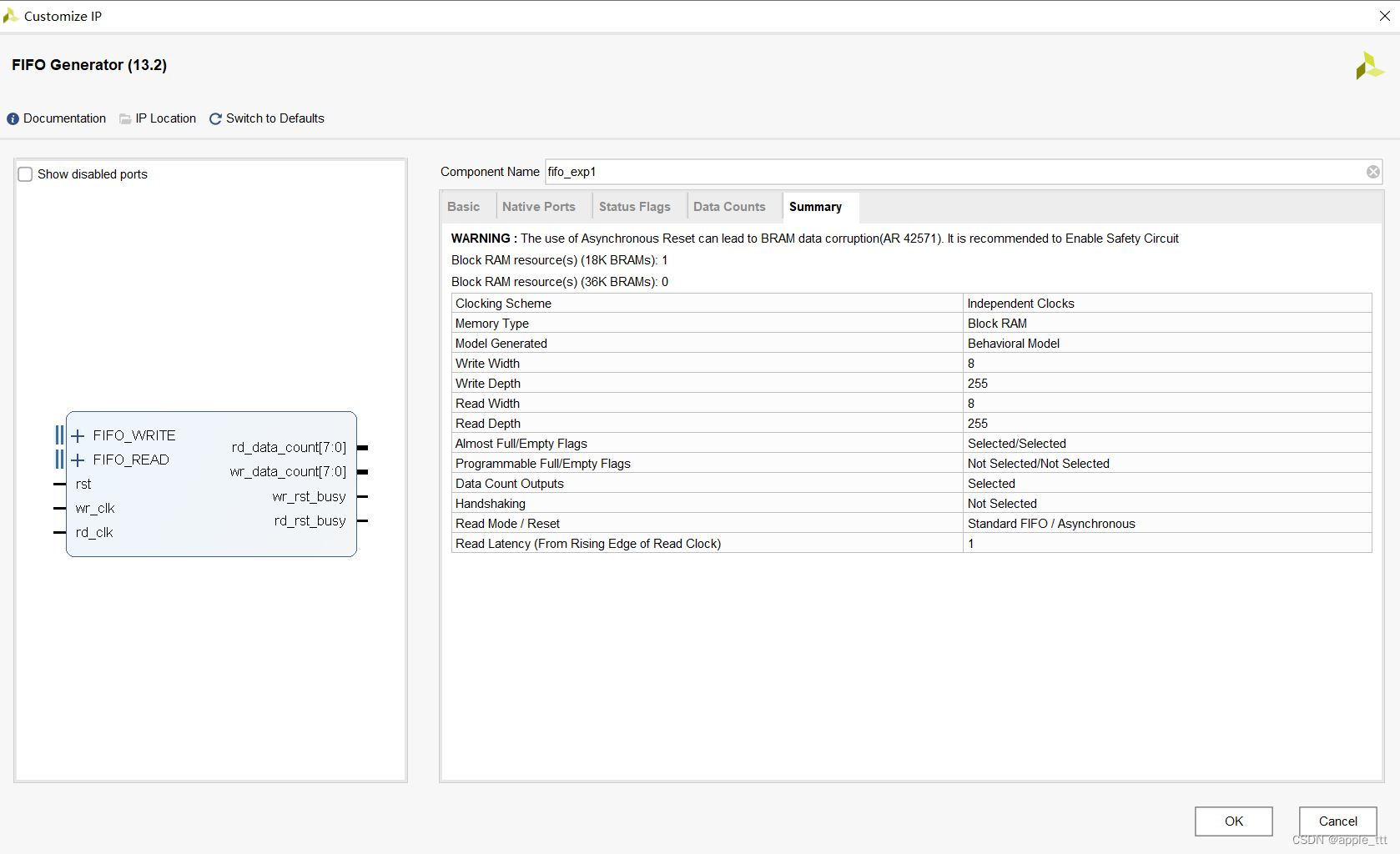
IP核定制的最后一面永远是Summary界面,帮助我们进行一个回顾和检查。
三、IP核测试
首先设计了写FIFO模块和读FIFO模块:
3.1 写fifo模块
- //-------------------------------------<写fifo模块>--------------------------------
- module fifo_wr(
- //-------------------<信号输入>-----------------------
- input clk, //系统时钟
- input rst, //复位信号
- input almost_empty, //FIFO将空信号
- input almost_full , //FIFO将满信号
- //-------------------<信号输出>-----------------------
- output reg fifo_wr_en, //FIFO写使能
- output reg [7:0] fifo_wr_data //写入FIFO的数据
- );
- //reg define
- reg [1:0] state ; //动作状态
- reg almost_empty_d0 ; //almost_empty 延迟一拍
- reg almost_empty_syn ; //almost_empty 延迟两拍
- reg [3:0] dly_cnt ; //延迟计数器
- //因为 almost_empty 信号是属于FIFO读时钟域的
- //所以要将其同步到写时钟域中
- always@( posedge clk ) begin
- if( rst ) begin
- almost_empty_d0 <= 1'b0 ;
- almost_empty_syn <= 1'b0 ;
- end
- else begin
- almost_empty_d0 <= almost_empty ;
- almost_empty_syn <= almost_empty_d0 ;
- end
- end
- //向FIFO中写入数据
- always @(posedge clk ) begin
- if(rst) begin
- fifo_wr_en <= 1'b0;
- fifo_wr_data <= 8'd0;
- state <= 2'd0;
- dly_cnt <= 4'd0;
- end
- else begin
- case(state)
- 2'd0: begin
- if(almost_empty_syn) begin //如果检测到FIFO将被读空
- state <= 2'd1; //就进入延时状态
- end
- else
- state <= state;
- end
- 2'd1: begin
- if(dly_cnt == 4'd10) begin //延时10拍
- //原因是FIFO IP核内部状态信号的更新存在延时
- //延迟10拍以等待状态信号更新完毕
- dly_cnt <= 4'd0;
- state <= 2'd2; //开始写操作
- fifo_wr_en <= 1'b1; //打开写使能
- end
- else
- dly_cnt <= dly_cnt + 4'd1;
- end
- 2'd2: begin
- if(almost_full) begin //等待FIFO将被写满
- fifo_wr_en <= 1'b0; //关闭写使能
- fifo_wr_data <= 8'd0;
- state <= 2'd0; //回到第一个状态
- end
- else begin //如果FIFO没有被写满
- fifo_wr_en <= 1'b1; //则持续打开写使能
- fifo_wr_data <= fifo_wr_data + 1'd1; //且写数据值持续累加
- end
- end
- default : state <= 2'd0;
- endcase
- end
- end
- endmodule
3.2 读FIFO模块
- //-------------------------------------<读fifo模块>--------------------------------
- module fifo_rd(
- //-------------------<信号输入>-----------------------
- input clk , // 时钟信号
- input rst , // 复位信号
- input [7:0] fifo_dout , // 从FIFO读出的数据
- input almost_full ,// FIFO将满信号
- input almost_empty,// FIFO将空信号
- //-------------------<信号输出>-----------------------
- output reg fifo_rd_en // FIFO读使能
- );
- //reg define
- reg [1:0] state ; // 动作状态
- reg almost_full_d0 ; // fifo_full 延迟一拍
- reg almost_full_syn ; // fifo_full 延迟两拍
- reg [3:0] dly_cnt ; // 延迟计数器
- //因为 fifo_full 信号是属于FIFO写时钟域的
- //所以要将其同步到读时钟域中
- always@( posedge clk ) begin
- if( rst ) begin
- almost_full_d0 <= 1'b0 ;
- almost_full_syn <= 1'b0 ;
- end
- else begin
- almost_full_d0 <= almost_full ;
- almost_full_syn <= almost_full_d0 ;
- end
- end
- //读出FIFO的数据
- always @(posedge clk ) begin
- if(rst) begin
- fifo_rd_en <= 1'b0;
- state <= 2'd0;
- dly_cnt <= 4'd0;
- end
- else begin
- case(state)
- 2'd0: begin
- if(almost_full_syn) //如果检测到FIFO将被写满
- state <= 2'd1; //就进入延时状态
- else
- state <= state;
- end
- 2'd1: begin
- if(dly_cnt == 4'd10) begin //延时10拍
- //原因是FIFO IP核内部状态信号的更新存在延时
- //延迟10拍以等待状态信号更新完毕
- dly_cnt <= 4'd0;
- state <= 2'd2; //开始读操作
- end
- else
- dly_cnt <= dly_cnt + 4'd1;
- end
- 2'd2: begin
- if(almost_empty) begin //等待FIFO将被读空
- fifo_rd_en <= 1'b0; //关闭读使能
- state <= 2'd0; //回到第一个状态
- end
- else //如果FIFO没有被读空
- fifo_rd_en <= 1'b1; //则持续打开读使能
- end
- default : state <= 2'd0;
- endcase
- end
- end
- endmodule
3.3 顶层模块
- module fifo_top(
- //-------------------<信号输入>-----------------------
- input sys_clk, //系统时钟
- input rst //复位信号
- );
- wire [7:0] din; //fifo的输入数据(写入的数据)
- wire wr_en; //写使能
- wire rd_en; //读使能
- wire [7:0] dout; //fifo的输出数据(读出的数据)
- wire full; //fifo满信号
- wire almost_full; //fifo将满标志
- wire empty; //fifo空标志
- wire almost_empty; //fifo将空标志
- wire [7:0]rd_data_count; //fifo写时钟域的数据计数
- wire [7:0]wr_data_count; //fifo读时钟域的数据计数
- wire wr_rst_busy;
- wire rd_data_count;
- //-------------------<IP核例化>-----------------------
- fifo_exp1 fifo1 (
- .rst (rst), // input wire rst
- .wr_clk (sys_clk), // input wire wr_clk
- .rd_clk (sys_clk), // input wire rd_clk
- .din (din), // input wire [7 : 0] din
- .wr_en (wr_en), // input wire wr_en
- .rd_en (rd_en), // input wire rd_en
- .dout (dout), // output wire [7 : 0] dout
- .full (full), // output wire full
- .almost_full (almost_full), // output wire almost_full
- .empty (empty), // output wire empty
- .almost_empty (almost_empty), // output wire almost_empty
- .rd_data_count (rd_data_count), // output wire [7 : 0] rd_data_count
- .wr_data_count (wr_data_count), // output wire [7 : 0] wr_data_count
- .wr_rst_busy (wr_rst_busy), // output wire wr_rst_busy
- .rd_rst_busy (rd_rst_busy) // output wire rd_rst_busy
- );
- //例化写FIFO模块
- fifo_wr fifo_wr_u1(
- .clk ( sys_clk ), // 写时钟
- .rst ( rst ), // 复位信号
- .fifo_wr_en ( wr_en ) , // fifo写请求
- .fifo_wr_data ( din ) , // 写入FIFO的数据
- .almost_empty ( almost_empty ), // fifo空信号
- .almost_full ( almost_full ) // fifo满信号
- );
- //例化读FIFO模块
- fifo_rd fifo_rd_u1(
- .clk ( sys_clk ), // 读时钟
- .rst ( rst ), // 复位信号
- .fifo_rd_en ( rd_en ), // fifo读请求
- .fifo_dout ( dout ), // 从FIFO输出的数据
- .almost_empty ( almost_empty ), // fifo空信号
- .almost_full ( almost_full ) // fifo满信号
- );
- endmodule
3.4 测试模块
- `timescale 1ns / 1ps
- module tb_ip_fifo( );
- // Inputs
- reg sys_clk;
- reg rst;
- // Instantiate the Unit Under Test (UUT)
- fifo_top tb1_fifo_top (
- .sys_clk (sys_clk),
- .rst (rst)
- );
- //Genarate the clk
- parameter PERIOD = 20;
- always begin
- sys_clk = 1'b0;
- #(PERIOD/2) sys_clk = 1'b1;
- #(PERIOD/2);
- end
- initial begin
- // Initialize Inputs
- rst = 1;
- // Wait 100 ns for global reset to finish
- #100 ;
- rst = 0;
- // Add stimulus here
- end
- endmodule
3.4 测试结果

通过看到FIFO如我们预期的写入和读出数据,读出的数据满足先入先出的原则。
四、总结
本文总结了FIFO IP核的使用方法,给出了各个配置参数的具体含义及配置方式,并对相关的设计进行了测试。
-
相关阅读:
Media Encoder 2024 for Mac媒体编码器安装教程ME2024安装包下载
基于微信小程序的电影院购票系统丨毕业设计源码
AsyncLocal<T>在链路追踪中的应用
编码技巧——MongoDB的过期时间
化工行业调研:中国二氧化碳(CO2)2028年市场规模将达到64.66亿元
面试高频手撕算法 - 01背包系列
Java高级学习栈(史上最详细的整合)
fastapi 在中间件中获取requestBody
网络缓冲区
优秀测试成长之路
- 原文地址:https://blog.csdn.net/apple_53311083/article/details/132471818
 https://blog.csdn.net/apple_53311083/article/details/132378996?spm=1001.2014.3001.5501