-
[EECS][Design Lab 3][All Carrot, No Stick] 实现目标线性轨迹运动 实现状态机的级联 距离控制实现避障
Lab report 3
2022 - 2023 the first semester
Course title: Experiments of Introduction to EECS I
Experiment title: Design Lab 3 (All Carrot, No Stick)
Experimenter: Zane Zhao 、Wenshuo Chen
[Specific experiments]
Goals: The overall goal of this lab is to build a robust capability for the robot to drive a route made up of linear path segments. We will do this in three stages:
• Implement a state machine that drives the robot in a straight line to a
goal specified in the coordinate system of its odometry.
• Make the robot traverse a sequence of linear segments by cascading a machine that generates target points with the machine that drives to a
target.
• Make the robot less of a danger to humanity by adding a ’reflex’ that
will make the robot stop when its path is blocked, and wait until it is
unblocked, then resume its trajectory.Step1 Collect resources
- moveBrainSkeleton.py: main brain file, which imports the next two files.
- ffSkeleton.py: template for your implementation of a figure-following state machine.
- dynamicMoveToPointSkeleton.py: template for your implementation of a behavior that drives the robot to a specified point.
- testFF.py: procedure for testing figure follower in idle. Not used when the brain is run.
- testMove.py: procedure for testing move to point in idle. Not used
when the brain is run.
Step2 Driven
Objective: Make a robot brain that can follow a path that is composed of a sequence of straight line segments.
The two simpler state machines we shall construct are:
- A GoalGenerator is a state machine. On each step, the input is an instance of io.SensorInput(which contains the robot’s sonar and odometry readings) and the output is an instance of
util.Point, which represents the target that the robot should drive toward. - A DynamicMoveToPoint state machine takes an input that is a tuple containing two items: the first is an instance of util.Point and the second is an instance of io.SensorInput. On each step, the state machine generates one instance of io.Action, which specifies a single step toward the specified util.Point
S1
Use sm.Cascade, sm.Parallel, sm.Constant and sm.Wire (which we can read about in the online software documentation, available from the Reference tab of the 6.01 home page, as well as in the readings) to construct a composite machine shown in Figure below.

For now, make a state machine (which serves the role of a GoalGenerator in Figure above) that always outputs the constant point util.Point(1.0, 0.5). Also, create a DynamicMoveToPoint state machine (Figure above) by making an instance of the dynamicMoveToPointSkeleton.DynamicMoveToPoint class.
Type your code for constructing this composite machine into moveBrainSkeleton.py, in place of None at the linemySM = None- 1
We can test our composite machine by running moveBrainSkeleton.py in soar. Select the bigEmptyWorld.py world. Each soar step should print a message (but there will be no motion of the robot)
In later steps, we will replace the code that generate these messages with code that moves the robot.
Step2.1 Odometry
Before we implement the module that controls the robot, we have to understand coordinate frames and how the robot reports its current location.
The robot has shaft encoders on each of its drive wheels that count (fractions of) rotations of the wheels. The robot processor uses these encoder counts to update an estimated pose (a term that means both position and orientation) of the robot in a global reference frame. This figure shows the reference frame in which the robot’s odometry is reported.
When the robot is turned on, the frame is initialized to have its origin at the robot’s center and the positive x axis pointing out the front of the robot. We can now think of that frame as being painted on the ground; as you move or rotate the robot, it keeps reporting its pose in that original frame. The pose has x, y, and θ components: x and y are its location, in meters, and θ is its rotation to the left, in radians.
Note that the pose reading doesn’t change if we pick up the real robot and move it without the wheels turning. It only knows that it has moved because of the turning of the wheels. And remember that the odometry is far from perfect: the wheels slip and the error (especially rotational error) compounds over time.Step2.2 Utilities
We will represent robot poses using the util.Pose class, which we can read about in the online software documentation.
The util module also defines a class util.Point for representing points in 2D space. Assume that p0 = util.Point(x0,y0) and p1 = util.Point(x1,y1)
then p0.angleTo(p1) returns the angle (in radians) between the x-axis and the vector from p0 to p1
p0.distance(p1) returns the Euclidean distance between p0 and p1, and p0.isNear(p1, distEps) returns a boolean equal to p0.distance(p1)
Assume that pose0 = util.Pose(x0,y0,theta0), then pose0.point() returns a point equal to util.Point(x0,y0).
These procedures may also be useful:
- util.nearAngle(angle1, angle2, angleEps),
- util.fixAnglePlusMinusPi(angle), and
- util.clip(value, minValue, maxValue).
For reference, we should also consult the Lab Infrastructure Guide. It’s a good place to go to remind ourself about how robots and brains work.

Step2.3 Driving to a point
Objective: Implement the DynamicMoveToPoint state machine, which directs the robot to perform an action to reach a goal Point.
Remember that the input to the DynamicMoveToPoint state machine is a tuple (goalPoint, sensors), where
- goalPoint is an instance of util.Point. This point specifies where the robot should drive (in the coordinate frame of the odometry).
- sensors is an instance of io.SensorInput. You can get the current odometry value with sensors.odometry, which is an instance of util.Pose.
The output of the DynamicMoveToPoint state machine should be an instance of io.Action that specifies the action to be taken by the robot during its next step. For example, to create an action with forward velocity 0.2 m/s and rotational velocity 0.1 radians/s, the output should be io.Action(fvel=0.2, rvel=0.1).
The robot should follow a (nearly) straight line from its current position to its goal point.
S2
Determine the action that should be output by the DynamicMoveToPoint state machine for the following input conditions. (Answers can simple commands such as ’move forward’ or ’rotate left’).
Current robot pose goalPoint Action (0.0,0.0,0.0) (1.0,0.5) rotate (0.0,0.0,π/2) (1.0,0.5) rotate (0.0,0.0, t a n − 1 0.5 tan^{-1}0.5 tan−10.5) (1.0,0.5) forward (1.0001,0.4999,0.0) (1.0,0.5) stop Think of a strategy for implementing the DynamicMoveToPoint state machine. Explain how that strategy will drive the robot to the goal point. The output of our state machine should depend only on the input ; it doesn’t need to use the state.
S3
Write code to implement our strategy in the file dynamicMoveToPointSkeleton.py.
-
First, test our code in idle, as follows. Open the file dynamicMoveToPointSkeleton.py,
comment out
from soar.io import io- 1
and uncomment
import lib601.io as io- 1
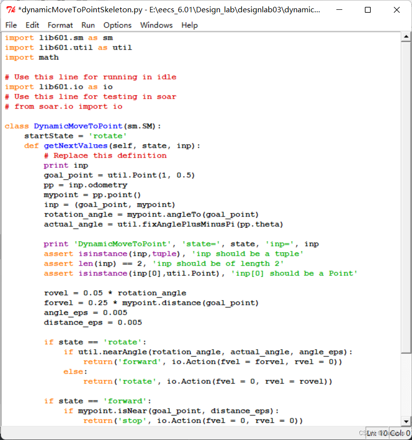
Now, test the code in idle, by running the testMove procedure from testMove.py.
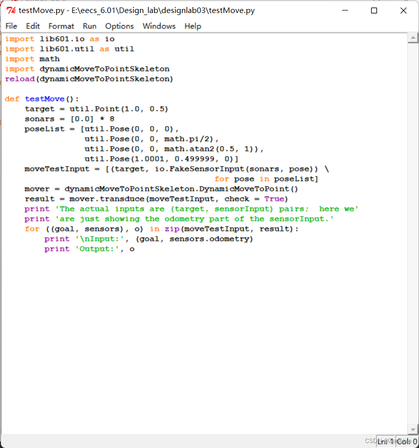
The test here has little impact on the following simulation and real car, so we won’t explain too much here
After our code works in idle, go back to soar’s version of io.py by editing dynamicMoveToPointSkeleton.py and commenting out
import lib601.io as io- 1
and uncommenting
from soar.io import io- 1
Now, test it using soar, by running moveBrainSkeleton.py in the simulated world bigEmptyWorld.py. Note that if we drag the robot around with your
mouse, the robot won’t know that it has been moved.For help in debugging, find the line verbose = False in the brain and change it to verbose = True;
that will cause soar to print out a lot of information on each step of the state machine that controls the brain.


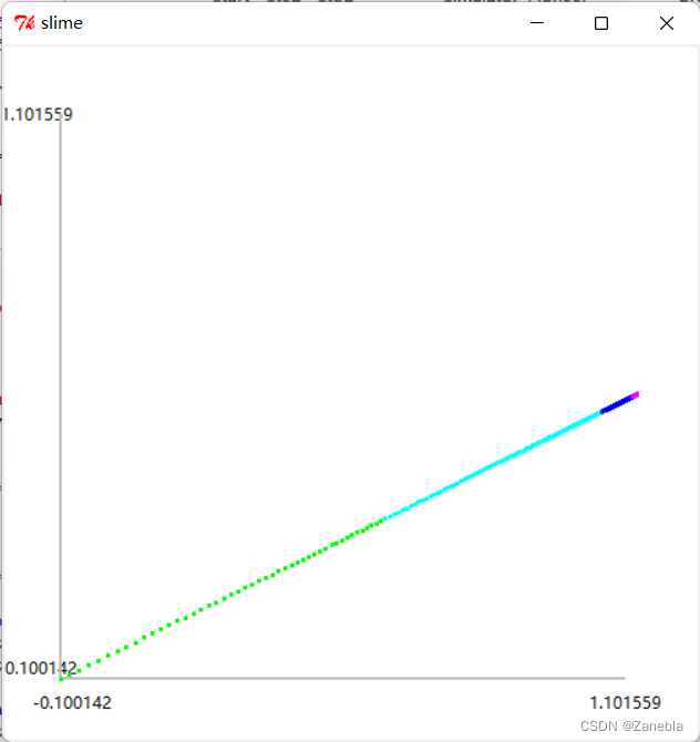
The moving track diagram of the car is as follows. At the beginning, the points are sparse because the car is fast, and then the points become more and more dense as the speed slows down.
Step3 Hip to be Square
Objective: Make the robot move in a square. Accomplish this (and other cool robot moves) by defining a new state machine class FollowFigure, which serves the role of being a GoalGenerator.
When we initialize the FollowFigure state machine, we will give it a list of way points, which are points that define a sequence of linear segments that the robot should traverse. The job of FollowFigure is to take instances of io.SensorInput as input and generate instances of util.Point as output; it should start out by generating the first point in the input sequence as output, and do that until the robot’s actual pose (found as sensorInput.odometry) is near that point; once the robot has gotten near the target point, the machine should switch to generating the next target point as output, etc. Even after the robot gets near the final point, the machine should just continue to generate that point as output.
So, for example, if we were to use the FollowFigure instance below as our target generator, it should cause the robot to move in a square.
squarePoints = [util.Point(0.5, 0.5), util.Point(0.0, 1.0), util.Point(-0.5, 0.5), util.Point(0.0, 0.0)] FollowFigure(squarePoints)- 1
- 2
- 3
If the robot is trying to follow the square above, and the FollowFigure state machine starts in its start state and sees odometry poses as input in the following sequence, what should its next state and output be on each step? The answer is as follows.
Current robot pose State Target point (0.0,0.0,0.0) rotate (0.5,0.5) (0.0,1.0,0.0) forward (-0.5,0.5) (0.499,0.501,2.0) rotate (0.0,1.0) (2.0,3.0,4.0) is equivalent to (0.0,1.0,4.0) rotate (-0.5,0.5) is equivalent to (1.5, 2.5) Define our FollowFigure state machine class in ffSkeleton.py. Test it in idle by running the testFF procedure in testFF.py, which contains the test cases shown above.
We do not explain here, mainly based on the simulation image results.
First, the code is as follows:
import lib601.sm as sm import lib601.util as util import math from soar.io import io class FollowFigure(sm.SM): def __init__(self, square): self.square = square self.index = 0 startState = 'rotate' def getNextValues(self, state, inp): p = self.square[self.index] print 'Next goal -->', p pp = inp.odometry mypoint = pp.point() inp = (p, mypoint) rotation_angle = mypoint.angleTo(p) actual_angle = util.fixAnglePlusMinusPi(pp.theta) print 'DynamicMoveToPoint', 'state=', state, 'inp=', inp rovel = abs(0.05 * rotation_angle) forvel = 0.15 * mypoint.distance(p) angle_eps = 0.005 distance_eps = 0.005 min_distance = min(io.SensorInput().sonars) if min_distance < 0.3: return('avoid',io.Action(fvel = 0, rvel = 0)) if state == 'rotate': if util.nearAngle(rotation_angle, actual_angle, angle_eps): return('forward', io.Action(fvel = forvel, rvel = 0)) else: return('rotate', io.Action(fvel = 0, rvel = rovel)) if state == 'forward': if mypoint.isNear(p, distance_eps): return('stop', io.Action(fvel = 0, rvel = 0)) else: return('forward', io.Action(fvel = forvel, rvel = 0)) if state == 'stop': self.index = self.index + 1 if self.index == len(self.square): self.index = 0 return('stop', io.Action(fvel = 0, rvel = 0)) else: return('rotate', io.Action(fvel = 0, rvel = rovel)) if state == 'avoid': if min_distance >= 0.3: return('rotate', io.Action(fvel = 0, rvel = rovel)) if min_distance < 0.3: return('avoid',io.Action(fvel = 0, rvel = 0)) return(state, io.Action())- 1
- 2
- 3
- 4
- 5
- 6
- 7
- 8
- 9
- 10
- 11
- 12
- 13
- 14
- 15
- 16
- 17
- 18
- 19
- 20
- 21
- 22
- 23
- 24
- 25
- 26
- 27
- 28
- 29
- 30
- 31
- 32
- 33
- 34
- 35
- 36
- 37
- 38
- 39
- 40
- 41
- 42
- 43
- 44
- 45
- 46
- 47
- 48
- 49
- 50
- 51
- 52
- 53
- 54
- 55
- 56
- 57
- 58
- 59
- 60
- 61

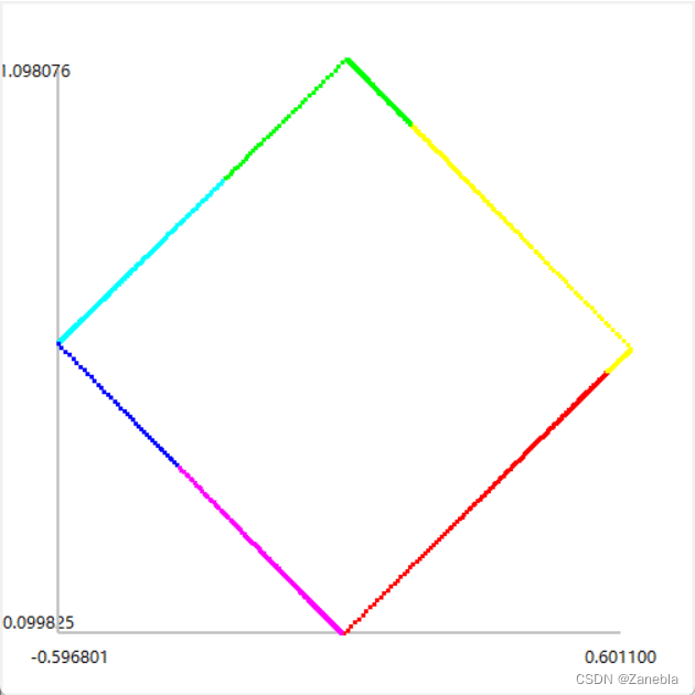
Use the original sequence

The image and data of car simulation
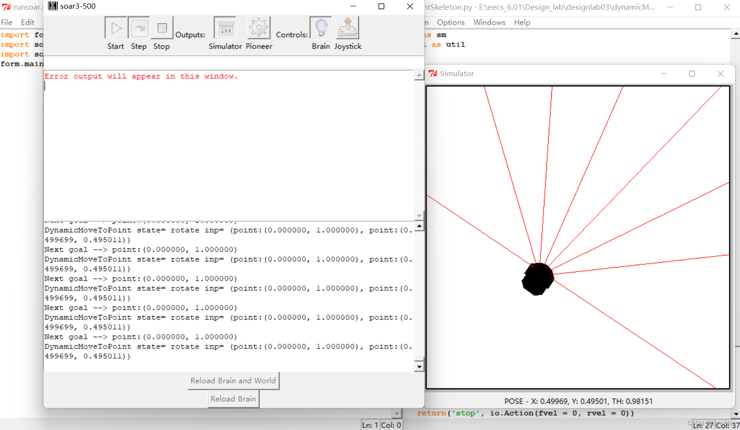
The final trajectory of the car is as follows
Change the sequence of ours

Reload the brain and world, run the soar again, The final trajectory of the car is as follows
Sorry, I lost my screenshot
Substitute an instance of the FollowFigure class for the GoalGenerator into the overall control architecture in moveBrainSkeleton.py, and debug it in bigEmptyWorld.py. Instead of going in a square, you could have your robot do a cool dance!

Step4 Avoiding Pedestrians
Objective: Your simulated robot, as it is currently constructed, tries to follow the specified figure and completely ignores its sonar sensors. We would like to define a new behavior that tries to follow the figure, but that monitors the front sonars and if any of them gets a reading less than 0.3, stops until the obstacle disappears, and then continues to follow the figure.
We can test this brain in simulation by dragging the robot around; its odometry reading won’t reflect that it has been dragged (it is as if you picked the robot up and ’kidnapped it’) so if we move it in front of a wall it should stop; and if we drag it away it should start to move again.
In the above code we have achieved this effect by setting a state “avoid” .
min_distance = min(io.SensorInput().sonars) if min_distance < 0.3: return('avoid',io.Action(fvel = 0, rvel = 0))- 1
- 2
- 3
if state == 'avoid': if min_distance >= 0.3: return('rotate', io.Action(fvel = 0, rvel = rovel)) if min_distance < 0.3: return('avoid',io.Action(fvel = 0, rvel = 0))- 1
- 2
- 3
- 4
- 5
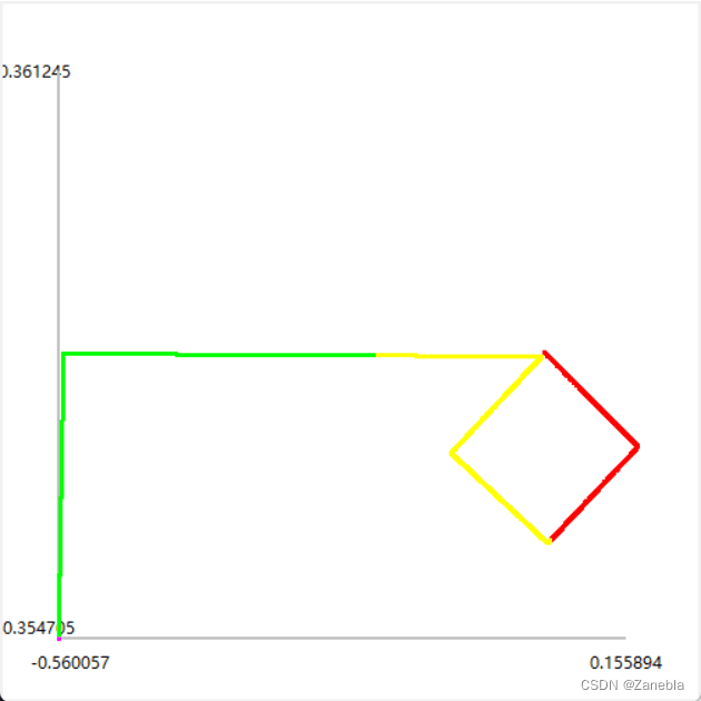
Step5 I am a ballerina
The final trajectory of the car is as follows
Step6 Conclusion and reflection
Compared with the previous experiment of walking along the wall, this experiment is easier to come up with a general framework, and the difficulty lies in the grasp of speed and error.
In addition, we also need to strengthen the data structure and algorithm foundation, so as to write more efficient and elegant code, and try our best to avoid the confusion of classes and objects, so as to make the code logic clearer
-
相关阅读:
JavaScript 中整数的安全范围
ChatGPT提示词(prompt)资源汇总
推荐系统-协同过滤在Spark中的实现
[附源码]计算机毕业设计JAVAjsp-线上摄影平台系统
简单聊一聊Javascript中的模块化
640.Solve the Equation
Clickhouse—MergeTree 数据生命周期
springboot项目静态资源映射
数字经济时代 企业的数据安全需要多维考虑
混合输入矩阵乘法的性能优化
- 原文地址:https://blog.csdn.net/m0_62629457/article/details/127418792