-
STM32使用库函数点灯实验
GPIO库函数介绍
重要函数:
1个初始化函数: void GPIO_Init(GPIO_TypeDef* GPIOx, GPIO_InitTypeDef* GPIO_InitStruct); 2个读取输入电平函数: uint8_t GPIO_ReadlnputDataBit(GPIO_TypeDef* GPIOx,uint16_t GPIO_Pin); uint16_t GPIO_ReadlnputData(GPIO_TypeDef* GPIOx); 2个读取输出电平函数: uint8_t GPIO_ReadOutputDataBit(GPIO_TypeDef* GPIOx,uint16_t GPIO_Pin); uint16_t GPIO_ReadOutputData(GPIO_TypeDef* GPIOx); 4个设置输出电平函数: void GPIO_SetBits(GPIO_TypeDef* GPIOx,uint16_t GPIO_Pin); void GPIO_ResetBits(GPIO_TypeDef* GPIOx,uint16_t GPIO_Pin); void GPIO_WriteBit(GPIO_TypeDef* GPIOx,uint16_t GPIO_Pin,BitAction BitVal); void GPIO_Write(GPIO_TypeDef* GPIOx,uint16_t PortVal);- 1
- 2
- 3
- 4
- 5
- 6
- 7
- 8
- 9
- 10
- 11
- 12
- 13
- 14
- 15
- 16
- 17
- 18
- 19
- 20
- 21
- 22
- 23
- 24
- 25
操作过程
操作IO口之前,必须使能对应的时钟位。
1.使能IO口时钟。调用函数RCC_APB2PeriphColckCmd();这个函数在stm32f10x_rcc.c文件中
不同的IO组,调用的时钟使能函数不一样。
2.初始化IO口模式。调用函数GPIO Init();
3.操作IO口,输出高低电平。
GPIO_SetBits();
GPIO_ResetBits();
程序
LED.c
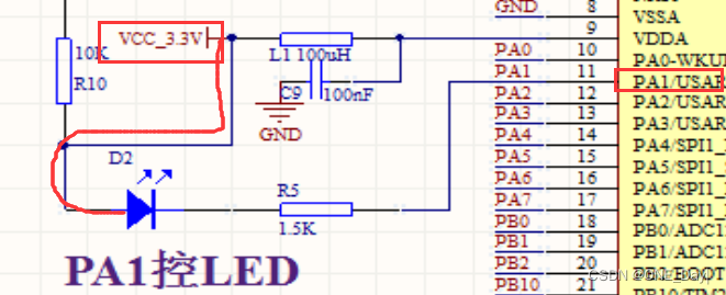
看开发板电路图,看LED接到了哪个引脚上,就初始化哪个端口的时钟,然后配置引脚模式,再用GPIO_Init初始化引脚
#include "LED.h" void LED_Init() { //定义GPIO的结构体变量 GPIO_InitTypeDef GPIO_InitStructure; //因为C8T6板LED接到了PA1,PA1挂到了APB2总线上,所以用APB2的时钟初始化函数 //时钟初始化函数在stm32f10x_rcc.c文件中 RCC_APB2PeriphClockCmd(RCC_APB2Periph_GPIOA,ENABLE); //对结构体内的变量赋初值 GPIO_InitStructure.GPIO_Pin = GPIO_Pin_1; //选择引脚1 GPIO_InitStructure.GPIO_Mode = GPIO_Mode_Out_PP; //GPIO模式设置为推挽输出 GPIO_InitStructure.GPIO_Speed = GPIO_Speed_50MHz; //GPIO的速度设为50MHz //调用GPIO_Init对结构体变量初始化,初始化的是GPIOA端口组 GPIO_Init(GPIOA,&GPIO_InitStructure); //根据电路图,设置GPIOA的Pin1引脚输出低电平,LED灯才亮 GPIO_ResetBits(GPIOA,GPIO_Pin_1); //GPIO_SetBits(GPIOA,GPIO_Pin_1); //设置PA1输出高电平,LED灯熄灭 }- 1
- 2
- 3
- 4
- 5
- 6
- 7
- 8
- 9
- 10
- 11
- 12
- 13
- 14
- 15
- 16
- 17
- 18
- 19
- 20
- 21
- 22
- 23
- 24
GPIO_ResetBits是清除引脚电平,也就是输出低电平,函数内部其实就是对端口位清除寄存器(GPIOx_BRR)进行赋值
/** * @brief Clears the selected data port bits. * @param GPIOx: where x can be (A..G) to select the GPIO peripheral. * @param GPIO_Pin: specifies the port bits to be written. * This parameter can be any combination of GPIO_Pin_x where x can be (0..15). * @retval None */ void GPIO_ResetBits(GPIO_TypeDef* GPIOx, uint16_t GPIO_Pin) { /* Check the parameters */ assert_param(IS_GPIO_ALL_PERIPH(GPIOx)); assert_param(IS_GPIO_PIN(GPIO_Pin)); GPIOx->BRR = GPIO_Pin; }- 1
- 2
- 3
- 4
- 5
- 6
- 7
- 8
- 9
- 10
- 11
- 12
- 13
- 14
- 15
注意:
手上的开发板LED的电路图表示LED灯是低电平点亮

问题:
实验时发现如果把PA1引脚输出低电平的函数GPIO_ResetBits注释掉或者删掉,LED灯仍然会被点亮

解决:
因为开发板上的LED是低电平点亮的,而GPIO_ResetBits函数操作的是寄存器BRR,BRR在复位时复位值是 0x0000 0000,所以BR1位为0,置0对对应的ODR1位不产生影响,而ODR1位是端口输出数据寄存器(GPIOx_ODR)的,该寄存器的复位值也是 0x0000 0000,也就是说,只要配置了PA1为输出模式,GPIOx_ODR寄存器是默认每一位都输出低电平的,这样ODR1位就是0,因为配置ODR寄存器的该位为0 LED灯是会亮的;
所以即使没有最后这一句GPIO_ResetBits(GPIOA,GPIO_Pin_1);设置引脚输出低电平,LED灯也是会被默认点亮
如果使用GPIO_SetBits输出高电平,则LED灯会被熄灭
-
相关阅读:
数据结构—查找方法改进流程
算法训练营day31,贪心算法5
李福攀:Kata安全容器在蚂蚁集团的应用实践
开关电源设计中 AP值的推导过程
OJ练习第183题——移动机器人
且看这个Node全栈框架,实现了个Cli终端引擎,可无限扩充命令集
Linux系统介绍
基于Java毕业设计高校共享机房管理系统的设计与实现源码+系统+mysql+lw文档+部署软件
Java低代码:jvs-list (子列表)表单回显及触发逻辑引擎配置说明
FFmpeg开发笔记(十七)Windows环境给FFmpeg集成字幕库libass
- 原文地址:https://blog.csdn.net/weixin_46251230/article/details/126632605
