-
块设备和总线
资源管理
数据结构
Linux 提供了一个通用构架,用于在内存中构建数据结构。这些结构描述了系统中可用的资源,使得内核代码能够管理和分配资源。注意,其中关键的数据结构是struct resource。
linux采用struct resource结构体来描述一个挂接在cpu总线上的设备实体(32位cpu的总线地址范围是0~4G)。/* * Resources are tree-like, allowing * nesting etc.. */ struct resource { //设备实体在cpu总线上的线性起始物理地址和结束物理地址 resource_size_t start; resource_size_t end; //描述这个设备实体的名称。这个名字可以随意起,但最好贴切 const char *name; //描述这个设备实体的一些共性和特性的标志位 unsigned long flags; unsigned long desc; /* struct resource是树形结构,链接parent、sibling、child规则: 1.每个子节点只有一个父节点 2.一个父节点可以有任意数目的子节点 3.同一个父节点的所有子节点,会链接到兄弟节点链表中 */ struct resource *parent, *sibling, *child; };- 1
- 2
- 3
- 4
- 5
- 6
- 7
- 8
- 9
- 10
- 11
- 12
- 13
- 14
- 15
- 16
- 17
- 18
- 19
- 20
- 21
linux需要管理4G物理总线的所有空间,所以挂接到总线上的形形色色的各种设备实体,这就需要链在一起,因此resource结构体提供了另外3个成员:指针parent、sibling和child:分别为指向父亲、兄弟和子资源的指针。
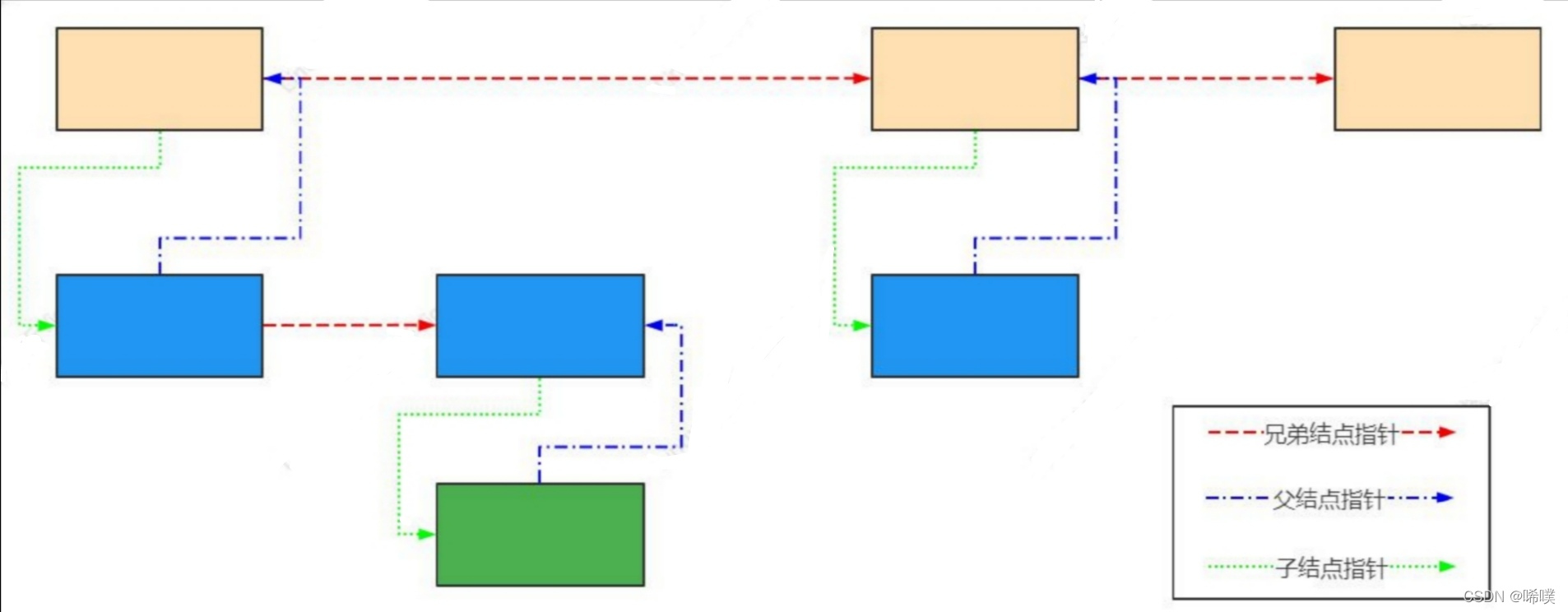
以root 为例,root->child指向root所有孩子中地址空间最小的一个;pchild->sibling是兄弟链表的开头,指向比自己地址空间大的兄弟。 注意父节点只有一个指针指向子节点,所有其他子节点都是通过兄弟节点链表进行访问。指向父节点的指针可以为空,说明没有更高层次的节点。请求资源和释放资源
为确保可靠地配置资源(无论何种类型),内核必须提供一种机制来分配和释放资源。一旦资源已经分配,则不能由任何其他驱动程序使用。请求和释放资源,无非是从资源树中添加和删除项而已。
请求资源
内核会扫描父节点的所有子节点,看是否有节点(资源)可以进行分配,内核不会再继续扫描更低层次的子节点。
内核提供了__request_resource 函数,用于请求一个资源区域。/* Return the conflict entry if you can't request it */ static struct resource * __request_resource(struct resource *root, struct resource *new) { resource_size_t start = new->start; resource_size_t end = new->end; struct resource *tmp, **p; if (end < start) return root; if (start < root->start) return root; if (end > root->end) return root; p = &root->child; for (;;) { tmp = *p; if (!tmp || tmp->start > end) { new->sibling = tmp; *p = new; new->parent = root; return NULL; } p = &tmp->sibling; if (tmp->end < start) continue; return tmp; } } /** * request_resource_conflict - request and reserve an I/O or memory resource * @root: root resource descriptor * @new: resource descriptor desired by caller * * Returns 0 for success, conflict resource on error. */ struct resource *request_resource_conflict(struct resource *root, struct resource *new) { struct resource *conflict; write_lock(&resource_lock); conflict = __request_resource(root, new); write_unlock(&resource_lock); return conflict; } /** * request_resource - request and reserve an I/O or memory resource * @root: root resource descriptor * @new: resource descriptor desired by caller * * Returns 0 for success, negative error code on error. */ int request_resource(struct resource *root, struct resource *new) { struct resource *conflict; conflict = request_resource_conflict(root, new); return conflict ? -EBUSY : 0; } EXPORT_SYMBOL(request_resource);- 1
- 2
- 3
- 4
- 5
- 6
- 7
- 8
- 9
- 10
- 11
- 12
- 13
- 14
- 15
- 16
- 17
- 18
- 19
- 20
- 21
- 22
- 23
- 24
- 25
- 26
- 27
- 28
- 29
- 30
- 31
- 32
- 33
- 34
- 35
- 36
- 37
- 38
- 39
- 40
- 41
- 42
- 43
- 44
- 45
- 46
- 47
- 48
- 49
- 50
- 51
- 52
- 53
- 54
- 55
- 56
- 57
- 58
- 59
- 60
- 61
- 62
释放资源
直接看代码,注意只是从树上拿下了节点。
static int __release_resource(struct resource *old, bool release_child) { struct resource *tmp, **p, *chd; p = &old->parent->child; for (;;) { tmp = *p; if (!tmp) break; if (tmp == old) { if (release_child || !(tmp->child)) { *p = tmp->sibling; } else { for (chd = tmp->child;; chd = chd->sibling) { chd->parent = tmp->parent; if (!(chd->sibling)) break; } *p = tmp->child; chd->sibling = tmp->sibling; } old->parent = NULL; return 0; } p = &tmp->sibling; } return -EINVAL; } /** * release_resource - release a previously reserved resource * @old: resource pointer */ int release_resource(struct resource *old) { int retval; write_lock(&resource_lock); retval = __release_resource(old, true); write_unlock(&resource_lock); return retval; } EXPORT_SYMBOL(release_resource);- 1
- 2
- 3
- 4
- 5
- 6
- 7
- 8
- 9
- 10
- 11
- 12
- 13
- 14
- 15
- 16
- 17
- 18
- 19
- 20
- 21
- 22
- 23
- 24
- 25
- 26
- 27
- 28
- 29
- 30
- 31
- 32
- 33
- 34
- 35
- 36
- 37
- 38
- 39
- 40
- 41
- 42
- 43
- 44
块IO
操作系统读取硬盘的时候,不会一个个扇区地读取,这样效率太低,而是一次性连续读取多个扇区,即一次性读取一个"块"(block)。这种由多个扇区组成的"块",是文件存取的最小单位。在磁盘上,最小可寻址单元是扇区,文件系统的最小寻址单元是块,且块不能比扇区小,得是它的2的n次方倍"块"的大小,最常见的是4KB,即连续八个 sector组成一个 block。
数据结构
块I/O的基本容器struct bio
struct bio 结构体包含了大量的基础信息,这些都是一个基本单元的属性,他们代表着当前这个 bio 的状态,比如是读还是写或者是一些特殊的操作命令等。以链表形式组织,因为其分散不连续性,又叫向量I/O。
struct bio是块I/O的基本容器,这个结构体描述的都只是元数据部分,实际数据都包含在紧跟其后的 bio_vec。/* * main unit of I/O for the block layer and lower layers (ie drivers and * stacking drivers) */ struct bio { //将与请求关联的bio组织到一个单链表中 struct bio *bi_next; /* request queue link */ //相关的块设备 struct block_device *bi_bdev; int bi_error; unsigned int bi_opf; /* bottom bits req flags, * top bits REQ_OP. Use * accessors. */ unsigned short bi_flags; /* status, etc and bvec pool number */ unsigned short bi_ioprio; struct bvec_iter bi_iter; /* Number of segments in this BIO after * physical address coalescing is performed. */ //当完成物理地址合并之后剩余的段的数量 unsigned int bi_phys_segments; /* * To keep track of the max segment size, we account for the * sizes of the first and last mergeable segments in this bio. */ //第一个和最后一个可合并的段大小 unsigned int bi_seg_front_size; unsigned int bi_seg_back_size; //关联bio的数量 atomic_t __bi_remaining; bio_end_io_t *bi_end_io; void *bi_private; #ifdef CONFIG_BLK_CGROUP /* * Optional ioc and css associated with this bio. Put on bio * release. Read comment on top of bio_associate_current(). */ struct io_context *bi_ioc; struct cgroup_subsys_state *bi_css; #ifdef CONFIG_BLK_DEV_THROTTLING_LOW void *bi_cg_private; struct blk_issue_stat bi_issue_stat; #endif #endif union { #if defined(CONFIG_BLK_DEV_INTEGRITY) struct bio_integrity_payload *bi_integrity; /* data integrity */ #endif }; //bio_vec的数目 unsigned short bi_vcnt; /* how many bio_vec's */ /* * Everything starting with bi_max_vecs will be preserved by bio_reset() */ unsigned short bi_max_vecs; /* max bvl_vecs we can hold */ //当前 bio 的引用计数,当该数据为 0 时才可以free atomic_t __bi_cnt; /* pin count */ struct bio_vec *bi_io_vec; /* the actual vec list */ struct bio_set *bi_pool; /* * We can inline a number of vecs at the end of the bio, to avoid * double allocations for a small number of bio_vecs. This member * MUST obviously be kept at the very end of the bio. */ //表示跟在 bio 后面的数据集合 struct bio_vec bi_inline_vecs[0]; };- 1
- 2
- 3
- 4
- 5
- 6
- 7
- 8
- 9
- 10
- 11
- 12
- 13
- 14
- 15
- 16
- 17
- 18
- 19
- 20
- 21
- 22
- 23
- 24
- 25
- 26
- 27
- 28
- 29
- 30
- 31
- 32
- 33
- 34
- 35
- 36
- 37
- 38
- 39
- 40
- 41
- 42
- 43
- 44
- 45
- 46
- 47
- 48
- 49
- 50
- 51
- 52
- 53
- 54
- 55
- 56
- 57
- 58
- 59
- 60
- 61
- 62
- 63
- 64
- 65
- 66
- 67
- 68
- 69
- 70
- 71
- 72
- 73
- 74
- 75
- 76
- 77
- 78
- 79
- 80
- 81
bio数据的最小单位struct bio_vec
bio_vec 是组成 bio 数据的最小单位,他包含了一块数据所在的页,这块数据所在的页内偏移以及长度,通过这些信息就可以很清晰的描述数据具体位于什么位置。
struct bio_vec { //指向用于数据传输的页对应的page实例 struct page *bv_page; //指定用于数据传输的字节数 unsigned int bv_len; //页内偏移,一般为0,因为页的边界一般用于io操作的边界 unsigned int bv_offset; };- 1
- 2
- 3
- 4
- 5
- 6
- 7
- 8
通过对这些数据的整合,可以将他们添加到 SGL(散列表) 中直接发送给后端硬件设备。
bio的几个数据结构之间的关系
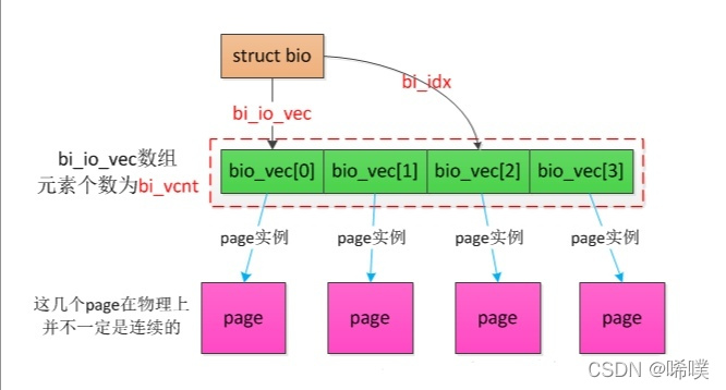
关于bio,还有两点要注意:- 一个bio所请求的数据在块设备中是连续的,对于不连续的数据块需要放到多个bio中。
- 一个bio所携带的数据大小是有上限的,该上限值由bi_max_vecs指定,超过上限的数据块必须放到多个bio中。
IO调度器
IO调度器是操作系统用来决定块设备上IO操作提交顺序的方法。存在的目的有两个,一是提高IO吞吐量,二是降低IO响应时间。然而IO吞吐量和IO响应时间往往是矛盾的,为了尽量平衡这两者,IO调度器提供了多种调度算法来适应不同的IO请求场景。
IO调度器作用主要是为了减少磁盘转动的需求。主要通过2种方式实现:合并和排序。具体来说,每个设备都会自己去对应请求队列,所有的请求在被处理之前都会在请求队列上。 在新来一个请求的时候如果发现这个请求和前面的某个请求的磁盘位置是相邻的,那么就可以合并为一个请求。如果不能找到合并的,就会按照磁盘的转动方向进行排序。通常IO 调度器的作用就是为了在进行合并和排序的同时,也不会太影响单个请求的处理时间。常用调度算法
NOOP算法
NOOP算法又叫电梯调度算法,是一种输入输出调度算法。NOOP, No Operation,什么都不做,请求来一个处理一个。这种方式实现起来简单,也更有效。问题就是disk seek 太多,对于传统磁盘,这是不能接受的,但对于SSD 就可以,因为SSD不需要转动。
主要原理是,将输入输出请求放到一个FIFO队列中,然后按次序执行队列中的输入输出请求。当来一个新请求时:- 如果能合并就合并
- 如果不能合并,就会尝试排序。如果队列上的请求都已经很老了,这个新的请求就不能插队,只能放到最后面,否则就插到合适的位置
- 如果既不能合并,又没有合适的位置插入,就放到请求队列的最后
适用场景:
- 在不希望修改输入输出请求先后顺序的场景下
- 在输入输出之下具有更加智能调度算法的设备,如NAS存储设备
- 上层应用程序已经精心优化过的输入输出请求
- 非旋转磁头式的磁盘设备,如SSD
下面看代码
struct elevator_ops { //将两个请求合并成一个请求 //在合并后会执行相关的清理工作,返回io调度器当中因合并而不再需要的数据 elevator_merge_fn *elevator_merge_fn; elevator_merged_fn *elevator_merged_fn; elevator_merge_req_fn *elevator_merge_req_fn; elevator_allow_bio_merge_fn *elevator_allow_bio_merge_fn; elevator_allow_rq_merge_fn *elevator_allow_rq_merge_fn; elevator_bio_merged_fn *elevator_bio_merged_fn; elevator_dispatch_fn *elevator_dispatch_fn; elevator_add_req_fn *elevator_add_req_fn; elevator_activate_req_fn *elevator_activate_req_fn; elevator_deactivate_req_fn *elevator_deactivate_req_fn; elevator_completed_req_fn *elevator_completed_req_fn; //分别查找给定请求的前一个和后一个请求 //在进行合并时,这两个函数的作用最大 elevator_request_list_fn *elevator_former_req_fn; elevator_request_list_fn *elevator_latter_req_fn; elevator_init_icq_fn *elevator_init_icq_fn; /* see iocontext.h */ elevator_exit_icq_fn *elevator_exit_icq_fn; /* ditto */ //分别在创建新请求和释放回内存管理子系统时调用 //这两个函数使用io调度器可以分配、初始化、释放用于管理的数据结构 elevator_set_req_fn *elevator_set_req_fn; elevator_put_req_fn *elevator_put_req_fn; elevator_may_queue_fn *elevator_may_queue_fn; //分别在队列初始化和释放时调用,与构造函数和析构函数类似 elevator_init_fn *elevator_init_fn; elevator_exit_fn *elevator_exit_fn; elevator_registered_fn *elevator_registered_fn; };- 1
- 2
- 3
- 4
- 5
- 6
- 7
- 8
- 9
- 10
- 11
- 12
- 13
- 14
- 15
- 16
- 17
- 18
- 19
- 20
- 21
- 22
- 23
- 24
- 25
- 26
- 27
- 28
- 29
- 30
- 31
- 32
- 33
- 34
- 35
- 36
- 37
- 38
每个 IO 调度器都封装在下列数据结构中,其中还包含了供内核使用的其他信息
/* * identifies an elevator type, such as AS or deadline */ struct elevator_type { /* managed by elevator core */ struct kmem_cache *icq_cache; /* fields provided by elevator implementation */ union { struct elevator_ops sq; struct elevator_mq_ops mq; } ops; size_t icq_size; /* see iocontext.h */ size_t icq_align; /* ditto */ struct elv_fs_entry *elevator_attrs; char elevator_name[ELV_NAME_MAX]; struct module *elevator_owner; bool uses_mq; #ifdef CONFIG_BLK_DEBUG_FS const struct blk_mq_debugfs_attr *queue_debugfs_attrs; const struct blk_mq_debugfs_attr *hctx_debugfs_attrs; #endif /* managed by elevator core */ char icq_cache_name[ELV_NAME_MAX + 6]; /* elvname + "_io_cq" */ //内核将所有io调度器放在一个标准的双链表中 //链表元素是list成员,链表头是全局变量 struct list_head list; };- 1
- 2
- 3
- 4
- 5
- 6
- 7
- 8
- 9
- 10
- 11
- 12
- 13
- 14
- 15
- 16
- 17
- 18
- 19
- 20
- 21
- 22
- 23
- 24
- 25
- 26
- 27
- 28
- 29
- 30
CFQ算法
顾名思义,完全公平调度算法。它试图为竞争块设备使用权的所有进程分配一个请求队列和一个时间片,在调度器分配给进程的时间片内,进程可以将其读写请求发送给底层块设备,当进程的时间片消耗完,进程的请求队列将被挂起,等待调度。每个进程的时间片和每个进程的队列长度取决于进程的IO优先级,每个进程都会有一个IO优先级,CFQ调度器将会将其作为考虑的因素之一,来确定该进程的请求队列何时可以获取块设备的使用权。
IO优先级从高到低可以分为三大类:- RT(real time)
- BE(best try)
- IDLE(idle)
其中RT和BE又可以再划分为8个子优先级。可以通过ionice 去查看和修改。 优先级越高,被处理的越早,用于这个进程的时间片也越多,一次处理的请求数也会越多。
实际上,我们已经知道CFQ调度器的公平是针对于进程而言的,而只有同步请求(read或syn write)才是针对进程而存在的,他们会放入进程自身的请求队列,而所有同优先级的异步请求,无论来自于哪个进程,都会被放入公共的队列,异步请求的队列总共有8(RT)+8(BE)+1(IDLE)=17个。从Linux 2.6.18起,CFQ作为默认的IO调度算法。对于通用的服务器来说,CFQ是较好的选择。
DEADLINE算法
DEADLINE在CFQ的基础上,解决了IO请求饿死的极端情况。除了CFQ本身具有的IO排序队列之外,DEADLINE额外分别为读IO和写IO提供了FIFO队列。读FIFO队列的最大等待时间为500ms,写FIFO队列的最大等待时间为5s(当然这些参数都是可以手动设置的)。FIFO队列内的IO请求优先级要比CFQ队列中的高,,而读FIFO队列的优先级又比写FIFO队列的优先级高。优先级可以表示如下:
FIFO(Read) > FIFO(Write) > CFQ
deadline 实际上是对Elevator 的一种改进,一是避免有些请求太长时间不能被处理,二是区别对待读操作和写操作。对IO压力比较重,且功能比较单一的场景,例如数据库服务器,deadline算法较为适用。Anticipatory算法
已经在2010年从内核中去掉了。该算法推迟I/O请求,以期能对它们进行排序,获得最高的效率。在每次处理完读请求之后,不是立即返回,而是等待一小段时间(默认6ms)。在这段时间内,任何来自临近区域的请求都被立即执行,超时以后,继续原来的处理。
总线
介绍一下总线。
系统总线上传送的信息包括数据信息、地址信息、控制信息,因此,系统总线包含有三种不同功能的总 线 , 即数 据 总 线 DB ( Data Bus ) 、地 址 总 线 AB(Address Bus)和控制总线 CB(Control Bus)。- 数据总线:将cpu的数据传送到存储器或io接口等部件,也可将其他部件的数据传送到cpu。数据总线上不仅传输狭义上的数据,也可以传输指定、代码、状态等数据。
- 地址总线:专门传送地址。由于地址只能从cpu传向外部存储器或io端口,所以地址总线总是单向的。
- 控制总线:用来传输控制信号和时序信号。
系统总线在微型计算机中的地位,如同人的神经中枢系统,CPU 通过系统总线对存储器的内容进行读写,同样通过总线,实现将 CPU 内数据写入外设,或由外设读入 CPU。微型计算机都采用总线结构。总线就是用来传送信息的一组通信线。微型计算机通过系统总线将各部件连接到一起,实现了微型计算机内部各部件间的信息交换。
PCI 总线
PCI(peripheral component interconnect)总线是当前最流行的总线之一,它是由 Intel 公司推出的一种局部总线。它定义了 32 位数据总线,且可扩展为 64 位。PCI 总线主板插槽的体积比原 ISA 总线插槽还小,其功能比 VESA、ISA 有极大的改善,支持突发读写操作,最大传输速率可达 132MB/s,可同时支持多组外围设备。PCI 局部总线不能兼容现有的 ISA、EISA、MCA(micro channel architecture)总线,但它不受制于处理器,是基于奔腾等新一代微处理器而发展的总线。
PCI 总线规定了以下设计目标:- 支持高传输带宽,以适应具有大数据流的多媒体应用
- 简单且易于自动化配置附接的外设
- 平台独立性,即不绑定到特定的处理器类型或系统平台
PCI系统布局
设备标识
每个设备都有由一个16位编号来唯一标识,其中8位用于总线编号,5位用于插槽编号,3位用于功能编号。
- 总线编号:设备所在的总线编号,范围0-255
- 插槽编号:总线内部的一个唯一标识编号。一条总线最多可附接32个设备。不同总线上的插槽编号可能相同,但不会产生冲突,系统会帮我们解决。
- 功能编号:用于在一个扩展卡上面实现包括多个扩展设备的设备(IDE控制器、USB控制器等),扩展设备必须通过功能编号区分。PCI标准将一个设备上功能部件的最大数目定义为8。
配置空间
PCI有三个相互独立的物理地址空间,支持与PCI设备的通信:IO地址空间、配置空间、设备存储器空间。IO地址空间通过32位空间来用于与设备通信。用来与设备通信的端口最大4G,还取决于处理器类型(数据空间)。
对于配置空间。每个PCI设备有许多地址配置的寄存器,初始化时要通过这些寄存器来配置该设备的总线地址,一旦完成配置以后,CPU就可以访问该设备的各项资源了。PCI标准规定每个设备的配置寄存器组最多可以有256个连续的字节空间,开头64个字节叫头部,分为0型(PCI设备)和1型(PCI桥)头部,头部开头16个字节是设备的类型、型号和厂商等。这些头部寄存器除了地址配置的作用,还能使CPU能够探测到相应设备的存在,这样就不需要用户告诉系统都有哪些设备了,而是改由CPU通过一个号称枚举的过程自动扫描探测所有挂接在PCI总线上的设备。剩下192字节,称为配置空间的设备有关区。
由于PCI/PCIe设备分为Bridge和Agent两种,所以配置空间也有两种类型Agent类型
其中Agent的配置空间类型称为Type 00h
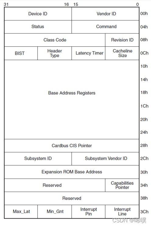
简单介绍其中的几个寄存器的意义:
Vendor ID,Device ID:标记了一个设备的生产厂商和具体的设备,比如Intel的设备Vendor ID通常是0x8086,Device ID就需要厂家自定义了,总之能够识别到具体是哪个设备就可以了。
Status:设备状态字,具体每个BIT的意义见下图
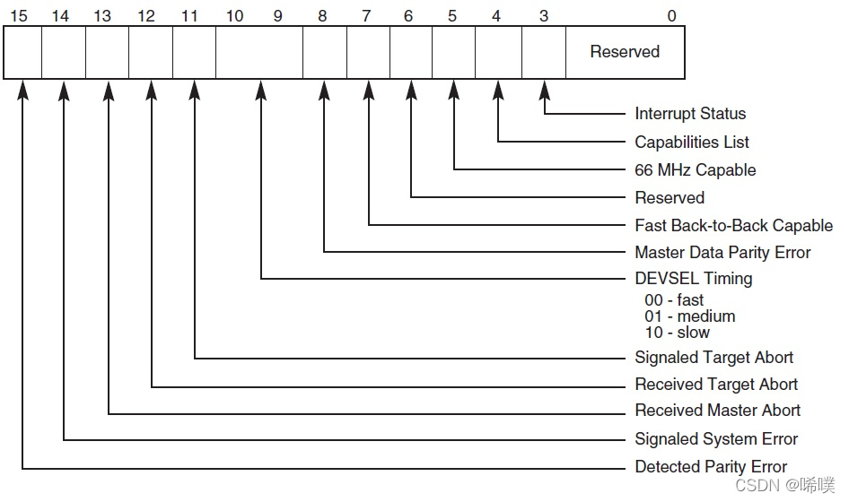
Command:设备状态字
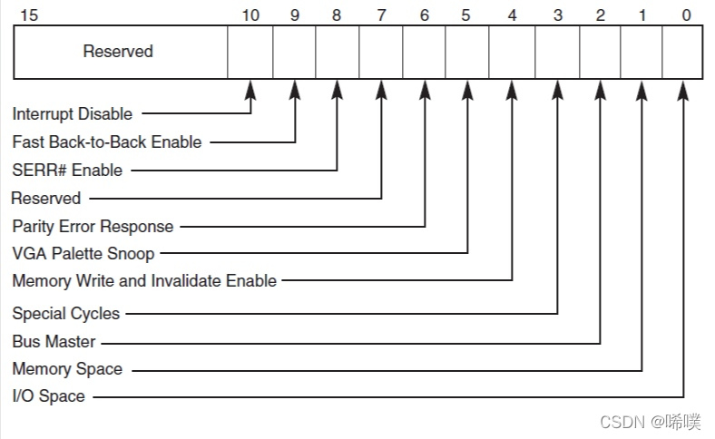
Base Address Registers:决定PCI/PCIe设备空间映射到系统空间具体位置的寄存器,映射方式有两种,分别是IO和Memory映射

Bridge类型
下面是Bridge的配置空间,它的类型被称为Type 01h

Type 01h中也有Vendor ID,Device ID,Status,Command等寄存器。
需要注意的是这里的BAR计算得到的系统空间是该桥下挂的所有设备的系统空间的总和。Subordinate Bus Number、Secondary Bus Number和Primary Bus Number,这些寄存器共同确定了该桥上行和下行的所有Bus号。数据结构
在内核中,系统为PCI驱动程序提供了一套框架。
系统中的各个总线由pci_bus实例表示struct pci_bus { //总线链表中的节点 struct list_head node; /* node in list of buses */ //桥接器所在父节点 struct pci_bus *parent; /* parent bus this bridge is on */ //子总线链表 struct list_head children; /* list of child buses */ //总线上设备的链表 struct list_head devices; /* list of devices on this bus */ //父总线所有的桥接器设备 struct pci_dev *self; /* bridge device as seen by parent */ struct list_head slots; /* list of slots on this bus; protected by pci_slot_mutex */ //导向总线的地址空间 struct resource *resource[PCI_BRIDGE_RESOURCE_NUM]; struct list_head resources; /* address space routed to this bus */ struct resource busn_res; /* bus numbers routed to this bus */ //访问一些配置信息的各个函数 struct pci_ops *ops; /* configuration access functions */ struct msi_controller *msi; /* MSI controller */ void *sysdata; /* hook for sys-specific extension */ struct proc_dir_entry *procdir; /* directory entry in /proc/bus/pci */ //总线号 unsigned char number; /* bus number */ //主桥接器编号 unsigned char primary; /* number of primary bridge */ unsigned char max_bus_speed; /* enum pci_bus_speed */ unsigned char cur_bus_speed; /* enum pci_bus_speed */ #ifdef CONFIG_PCI_DOMAINS_GENERIC int domain_nr; #endif char name[48]; unsigned short bridge_ctl; /* manage NO_ISA/FBB/et al behaviors */ pci_bus_flags_t bus_flags; /* inherited by child buses */ struct device *bridge; struct device dev; struct bin_attribute *legacy_io; /* legacy I/O for this bus */ struct bin_attribute *legacy_mem; /* legacy mem */ unsigned int is_added:1; };- 1
- 2
- 3
- 4
- 5
- 6
- 7
- 8
- 9
- 10
- 11
- 12
- 13
- 14
- 15
- 16
- 17
- 18
- 19
- 20
- 21
- 22
- 23
- 24
- 25
- 26
- 27
- 28
- 29
- 30
- 31
- 32
- 33
- 34
- 35
- 36
- 37
- 38
- 39
- 40
- 41
- 42
- 43
- 44
pci_dev结构体表示各个设备、扩展卡和功能部件
/* * The pci_dev structure is used to describe PCI devices. */ struct pci_dev { //在总线设备链表中的节点 struct list_head bus_list; /* node in per-bus list */ //设备所在的总线 struct pci_bus *bus; /* bus this device is on */ //桥接器设备接通的总线 struct pci_bus *subordinate; /* bus this device bridges to */ //是挂钩,用于特定的硬件扩展 void *sysdata; /* hook for sys-specific extension */ //是/proc/bus/pci的目录项 struct proc_dir_entry *procent; /* device entry in /proc/bus/pci */ struct pci_slot *slot; /* Physical slot this device is in */ //编码过程中的设备和功能的索引 unsigned int devfn; /* encoded device & function index */ unsigned short vendor; unsigned short device; unsigned short subsystem_vendor; unsigned short subsystem_device; unsigned int class; /* 3 bytes: (base,sub,prog-if) */ u8 revision; /* PCI revision, low byte of class word */ u8 hdr_type; /* PCI header type (`multi' flag masked out) */ #ifdef CONFIG_PCIEAER u16 aer_cap; /* AER capability offset */ #endif u8 pcie_cap; /* PCIe capability offset */ u8 msi_cap; /* MSI capability offset */ u8 msix_cap; /* MSI-X capability offset */ u8 pcie_mpss:3; /* PCIe Max Payload Size Supported */ u8 rom_base_reg; /* which config register controls the ROM */ u8 pin; /* which interrupt pin this device uses */ u16 pcie_flags_reg; /* cached PCIe Capabilities Register */ unsigned long *dma_alias_mask;/* mask of enabled devfn aliases */ struct pci_driver *driver; /* which driver has allocated this device */ u64 dma_mask; /* Mask of the bits of bus address this device implements. Normally this is 0xffffffff. You only need to change this if your device has broken DMA or supports 64-bit transfers. */ struct device_dma_parameters dma_parms; pci_power_t current_state; /* Current operating state. In ACPI-speak, this is D0-D3, D0 being fully functional, and D3 being off. */ u8 pm_cap; /* PM capability offset */ unsigned int pme_support:5; /* Bitmask of states from which PME# can be generated */ unsigned int pme_interrupt:1; unsigned int pme_poll:1; /* Poll device's PME status bit */ unsigned int d1_support:1; /* Low power state D1 is supported */ unsigned int d2_support:1; /* Low power state D2 is supported */ unsigned int no_d1d2:1; /* D1 and D2 are forbidden */ unsigned int no_d3cold:1; /* D3cold is forbidden */ unsigned int bridge_d3:1; /* Allow D3 for bridge */ unsigned int d3cold_allowed:1; /* D3cold is allowed by user */ unsigned int mmio_always_on:1; /* disallow turning off io/mem decoding during bar sizing */ unsigned int wakeup_prepared:1; unsigned int runtime_d3cold:1; /* whether go through runtime D3cold, not set for devices powered on/off by the corresponding bridge */ unsigned int ignore_hotplug:1; /* Ignore hotplug events */ unsigned int hotplug_user_indicators:1; /* SlotCtl indicators controlled exclusively by user sysfs */ unsigned int d3_delay; /* D3->D0 transition time in ms */ unsigned int d3cold_delay; /* D3cold->D0 transition time in ms */ #ifdef CONFIG_PCIEASPM struct pcie_link_state *link_state; /* ASPM link state */ #endif pci_channel_state_t error_state; /* current connectivity state */ struct device dev; /* Generic device interface */ int cfg_size; /* Size of configuration space */ /* * Instead of touching interrupt line and base address registers * directly, use the values stored here. They might be different! */ unsigned int irq; struct resource resource[DEVICE_COUNT_RESOURCE]; /* I/O and memory regions + expansion ROMs */ bool match_driver; /* Skip attaching driver */ /* These fields are used by common fixups */ unsigned int transparent:1; /* Subtractive decode PCI bridge */ unsigned int multifunction:1;/* Part of multi-function device */ /* keep track of device state */ unsigned int is_added:1; unsigned int is_busmaster:1; /* device is busmaster */ unsigned int no_msi:1; /* device may not use msi */ unsigned int no_64bit_msi:1; /* device may only use 32-bit MSIs */ unsigned int block_cfg_access:1; /* config space access is blocked */ unsigned int broken_parity_status:1; /* Device generates false positive parity */ unsigned int irq_reroute_variant:2; /* device needs IRQ rerouting variant */ unsigned int msi_enabled:1; unsigned int msix_enabled:1; unsigned int ari_enabled:1; /* ARI forwarding */ unsigned int ats_enabled:1; /* Address Translation Service */ unsigned int is_managed:1; unsigned int needs_freset:1; /* Dev requires fundamental reset */ unsigned int state_saved:1; unsigned int is_physfn:1; unsigned int is_virtfn:1; unsigned int reset_fn:1; unsigned int is_hotplug_bridge:1; unsigned int is_thunderbolt:1; /* Thunderbolt controller */ unsigned int __aer_firmware_first_valid:1; unsigned int __aer_firmware_first:1; unsigned int broken_intx_masking:1; unsigned int io_window_1k:1; /* Intel P2P bridge 1K I/O windows */ unsigned int irq_managed:1; unsigned int has_secondary_link:1; unsigned int non_compliant_bars:1; /* broken BARs; ignore them */ pci_dev_flags_t dev_flags; atomic_t enable_cnt; /* pci_enable_device has been called */ u32 saved_config_space[16]; /* config space saved at suspend time */ struct hlist_head saved_cap_space; struct bin_attribute *rom_attr; /* attribute descriptor for sysfs ROM entry */ int rom_attr_enabled; /* has display of the rom attribute been enabled? */ struct bin_attribute *res_attr[DEVICE_COUNT_RESOURCE]; /* sysfs file for resources */ struct bin_attribute *res_attr_wc[DEVICE_COUNT_RESOURCE]; /* sysfs file for WC mapping of resources */ #ifdef CONFIG_PCIE_PTM unsigned int ptm_root:1; unsigned int ptm_enabled:1; u8 ptm_granularity; #endif #ifdef CONFIG_PCI_MSI const struct attribute_group **msi_irq_groups; #endif struct pci_vpd *vpd; #ifdef CONFIG_PCI_ATS union { struct pci_sriov *sriov; /* SR-IOV capability related */ struct pci_dev *physfn; /* the PF this VF is associated with */ }; u16 ats_cap; /* ATS Capability offset */ u8 ats_stu; /* ATS Smallest Translation Unit */ atomic_t ats_ref_cnt; /* number of VFs with ATS enabled */ #endif phys_addr_t rom; /* Physical address of ROM if it's not from the BAR */ size_t romlen; /* Length of ROM if it's not from the BAR */ char *driver_override; /* Driver name to force a match */ unsigned long priv_flags; /* Private flags for the pci driver */ };- 1
- 2
- 3
- 4
- 5
- 6
- 7
- 8
- 9
- 10
- 11
- 12
- 13
- 14
- 15
- 16
- 17
- 18
- 19
- 20
- 21
- 22
- 23
- 24
- 25
- 26
- 27
- 28
- 29
- 30
- 31
- 32
- 33
- 34
- 35
- 36
- 37
- 38
- 39
- 40
- 41
- 42
- 43
- 44
- 45
- 46
- 47
- 48
- 49
- 50
- 51
- 52
- 53
- 54
- 55
- 56
- 57
- 58
- 59
- 60
- 61
- 62
- 63
- 64
- 65
- 66
- 67
- 68
- 69
- 70
- 71
- 72
- 73
- 74
- 75
- 76
- 77
- 78
- 79
- 80
- 81
- 82
- 83
- 84
- 85
- 86
- 87
- 88
- 89
- 90
- 91
- 92
- 93
- 94
- 95
- 96
- 97
- 98
- 99
- 100
- 101
- 102
- 103
- 104
- 105
- 106
- 107
- 108
- 109
- 110
- 111
- 112
- 113
- 114
- 115
- 116
- 117
- 118
- 119
- 120
- 121
- 122
- 123
- 124
- 125
- 126
- 127
- 128
- 129
- 130
- 131
- 132
- 133
- 134
- 135
- 136
- 137
- 138
- 139
- 140
- 141
- 142
- 143
- 144
- 145
- 146
- 147
- 148
- 149
- 150
- 151
- 152
- 153
- 154
- 155
- 156
每个驱动程序都通过pci_driver的实例描述
struct pci_driver { struct list_head node; const char *name; const struct pci_device_id *id_table; /* must be non-NULL for probe to be called */ int (*probe) (struct pci_dev *dev, const struct pci_device_id *id); /* New device inserted */ void (*remove) (struct pci_dev *dev); /* Device removed (NULL if not a hot-plug capable driver) */ int (*suspend) (struct pci_dev *dev, pm_message_t state); /* Device suspended */ int (*suspend_late) (struct pci_dev *dev, pm_message_t state); int (*resume_early) (struct pci_dev *dev); int (*resume) (struct pci_dev *dev); /* Device woken up */ void (*shutdown) (struct pci_dev *dev); int (*sriov_configure) (struct pci_dev *dev, int num_vfs); /* PF pdev */ const struct pci_error_handlers *err_handler; struct device_driver driver; struct pci_dynids dynids; };- 1
- 2
- 3
- 4
- 5
- 6
- 7
- 8
- 9
- 10
- 11
- 12
- 13
- 14
- 15
- 16
PCI 驱动程序可以通过 pci_register_driver()注册。该函数十分简单,其主要任务是,对相关函数已经分配的一个 pci_driver实例,填充一些剩余的字段。
/** * __pci_register_driver - register a new pci driver * @drv: the driver structure to register * @owner: owner module of drv * @mod_name: module name string * * Adds the driver structure to the list of registered drivers. * Returns a negative value on error, otherwise 0. * If no error occurred, the driver remains registered even if * no device was claimed during registration. */ int __pci_register_driver(struct pci_driver *drv, struct module *owner, const char *mod_name) { /* initialize common driver fields */ drv->driver.name = drv->name; drv->driver.bus = &pci_bus_type; drv->driver.owner = owner; drv->driver.mod_name = mod_name; spin_lock_init(&drv->dynids.lock); INIT_LIST_HEAD(&drv->dynids.list); /* register with core */ return driver_register(&drv->driver); } EXPORT_SYMBOL(__pci_register_driver);- 1
- 2
- 3
- 4
- 5
- 6
- 7
- 8
- 9
- 10
- 11
- 12
- 13
- 14
- 15
- 16
- 17
- 18
- 19
- 20
- 21
- 22
- 23
- 24
- 25
- 26
- 27
pci设备配置寄存器,对应结构体pci_device_id
struct pci_device_id { //厂商、设备的id,与配置空间中的对应 __u32 vendor, device; /* Vendor and device ID or PCI_ANY_ID*/ //子系统的id __u32 subvendor, subdevice; /* Subsystem ID's or PCI_ANY_ID */ //(class,subclass,prog-if)三元组 __u32 class, class_mask; /* (class,subclass,prog-if) triplet */ //驱动程序的私有数据 kernel_ulong_t driver_data; /* Data private to the driver */ };- 1
- 2
- 3
- 4
- 5
- 6
- 7
- 8
- 9
- 10
最后,简单说明一下linux启动过程。
通电后,cpu会自动把程序计数器设为cpu厂商设计的某个值。然后执行引导程序,引导程序会把内核加载到内存,然后执行内核。嵌入式设备通常用NOR闪存作为只读存储器来存储引导程序。kernel_entry()->start_kernel()- 1
-
相关阅读:
Redis 分布式锁
基于requests框架实现接口自动化测试项目实战
Android Fragment 要你何用?2.0版本
python-UnitTest学习笔记
React 配置别名 @ ( js/ts 项目中通过 webpack.config.js 配置)
水体悬浮颗粒物含量
10、MyBatis的缓存
L4W2KT作业 Keras教程
N皇后问题
如何让群晖Audio Station公开共享的本地音频公网可访问?
- 原文地址:https://blog.csdn.net/m0_65931372/article/details/126442257
