-
TinyRenderer学习笔记--从零构建软件渲染器
开始软件渲染器–tinyrenderer的学习
原项目地址 https://github.com/ssloy/tinyrenderer参考文档从零构建光栅器,tinyrenderer笔记(上) - 知乎 (zhihu.com)(非常不错!)
使用软件 vs2022,ps2019(查看TGA图片)
1、准备工作
首先,我们需要设置像素的颜色的功能
struct TGAColor { union { struct { unsigned char b, g, r, a;//四色 }; unsigned char raw[4]; unsigned int val; }; int bytespp; TGAColor():val(0),bytespp(1){} TGAColor(unsigned char R, unsigned char G, unsigned char B, unsigned char A) : b(B), g(G), r(R), a(A), bytespp(4) { } TGAColor(int v, int bpp) : val(v), bytespp(bpp) { } TGAColor(const TGAColor& c) : val(c.val), bytespp(c.bytespp) { } TGAColor(const unsigned char* p, int bpp) : val(0), bytespp(bpp) { for (int i = 0; i < bpp; i++) { raw[i] = p[i]; } } TGAColor& operator =(const TGAColor& c) { if (this != &c) { bytespp = c.bytespp; val = c.val; } return *this; } };- 1
- 2
- 3
- 4
- 5
- 6
- 7
- 8
- 9
- 10
- 11
- 12
- 13
- 14
- 15
- 16
- 17
- 18
- 19
- 20
- 21
- 22
- 23
- 24
- 25
- 26
- 27
- 28
- 29
- 30
- 31
- 32
- 33
- 34
- 35
- 36
- 37
- 38
- 39
- 40
- 41
- 42
此结构体可以储存颜色的三个分量信息的透明度信息。
下面这是关于TGA文件的相关操作,不是此次课程的重点,不再解释,有需求可查看项目源码。
class TGAImage { protected: unsigned char* data; int width; int height; int bytespp; bool load_rle_data(std::ifstream& in); bool unload_rle_data(std::ofstream& out); public: enum Format { GRAYSCALE = 1, RGB = 3, RGBA = 4 }; TGAImage(); TGAImage(int w, int h, int bpp); TGAImage(const TGAImage& img); bool read_tga_file(const char* filename); bool write_tga_file(const char* filename, bool rle = true); bool flip_horizontally(); bool flip_vertically(); bool scale(int w, int h); TGAColor get(int x, int y); bool set(int x, int y, TGAColor c); ~TGAImage(); TGAImage& operator =(const TGAImage& img); int get_width(); int get_height(); int get_bytespp(); unsigned char* buffer(); void clear(); };- 1
- 2
- 3
- 4
- 5
- 6
- 7
- 8
- 9
- 10
- 11
- 12
- 13
- 14
- 15
- 16
- 17
- 18
- 19
- 20
- 21
- 22
- 23
- 24
- 25
- 26
- 27
- 28
- 29
- 30
- 31
- 32
- 33
- 34
Lesson 1、学习Bresenham’s Line Drawing Algorithm
,用于在计算机中绘制直线段,其计算简单,仅仅只用了整数加法、减法和位移法。
我们尽量把精力放在渲染器的实现上,所以要尽可能减少对外部库的依赖,此次的实验只会涉及TGA文件的使用。
Vision 1
void line(int x0, int y0, int x1, int y1, TGAImage& image, TGAColor color) { for (float t = 0; t < 1; t += 0.1) { int x = x0 + (x1 - x0) * t; int y = y0 + (y1 - y0) * t; image.set(x, y, color); } }- 1
- 2
- 3
- 4
- 5
- 6
- 7
- 8
- 9
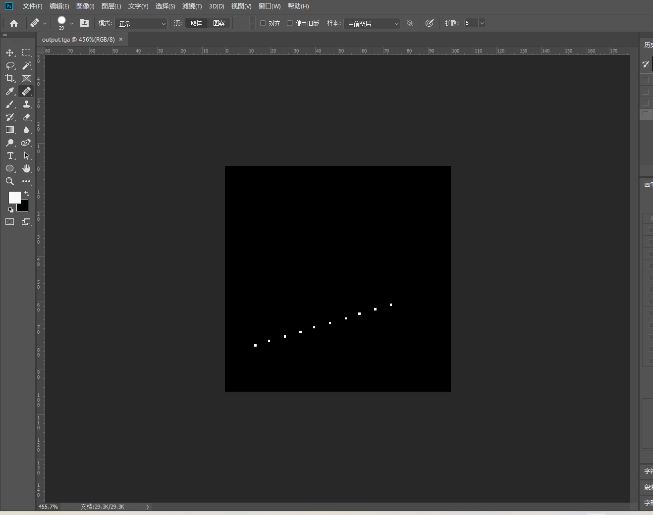
显然,这段代码只是输出了此线段上的某些像素点而已,如果我们要近似地得到整个线段,就需要将t设置成很小的值,会增加性能消耗。
Vision 2 void line(int x0, int y0, int x1, int y1, TGAImage& image, TGAColor color) { for (int x = x0; x <= x1; x++) { float t = (x - x0) / (float)(x1 - x0); int y = y0 * (1. - t) + y1 * t; image.set(x, y, color); } } line(13, 20, 80, 40, image, white); line(20, 13, 40, 80, image, red); line(80, 40, 13, 20, image, red);- 1
- 2
- 3
- 4
- 5
- 6
- 7
- 8
- 9
- 10
- 11
- 12
- 13
- 14
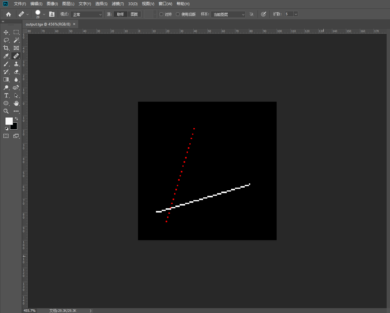
可以看出,第二条线和第三条线是有问题的,第二条线有空隙,第三条线没有绘制出来。第二条线的错误很明显,Y的改变速率远比X大,导致出现了空隙,有的点没有被绘制出来;第三条线的错误在于我们的代码默认了X1>X0,而第三条线不满足这个条件,导致线段不会被绘制出来。
Vision 3
void line(int x0, int y0, int x1, int y1, TGAImage& image, TGAColor color) { bool steep = false; if (std::abs(x0 - x1) < std::abs(y0 - y1)) { //直线斜率太大,需要翻转 std::swap(x0, y0); std::swap(x1, y1); steep = true; } if (x0 > x1) { //保证x1比x0大,否则t会出现负值 std::swap(x0, x1); std::swap(y0, y1); } for (int x = x0; x <= x1; x++) { float t = (x - x0) / (float)(x1 - x0); int y = y0 * (1. - t) + y1 * t; if (steep) { image.set(y, x, color);//翻转回来 } else { image.set(x, y, color); } } }- 1
- 2
- 3
- 4
- 5
- 6
- 7
- 8
- 9
- 10
- 11
- 12
- 13
- 14
- 15
- 16
- 17
- 18
- 19
- 20
- 21
- 22
- 23
- 24
- 25
- 26
- 27
- 28
- 29
- 30
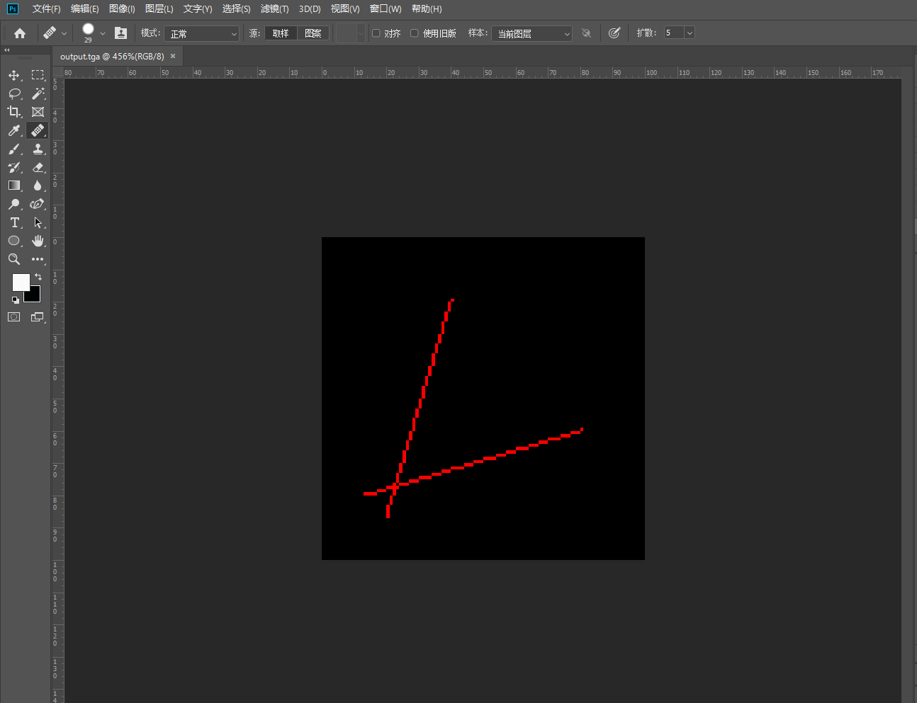
此版本解决了Vision 2的两个问题
Vision 4 最终版
void line(int x0, int y0, int x1, int y1, TGAImage& image, TGAColor color) { bool steep = false; if (std::abs(x0 - x1) < std::abs(y0 - y1)) { //直线斜率太大,需要翻转 std::swap(x0, y0); std::swap(x1, y1); steep = true; } if (x0 > x1) { //保证x1比x0大,否则t会出现负值 std::swap(x0, x1); std::swap(y0, y1); } int dx = x1 - x0; int dy = y1 - y0; int derror2 = std::abs(dy) * 2; int error2 = 0; int y = y0; for (int x = x0; x <= x1; x++) { if (steep) { image.set(y, x, color);//翻转回来 } else { image.set(x, y, color); } error2 += derror2; if (error2 > dx) { y += (y1 > y0 ? 1 : -1); error2 -= dx * 2; } } }- 1
- 2
- 3
- 4
- 5
- 6
- 7
- 8
- 9
- 10
- 11
- 12
- 13
- 14
- 15
- 16
- 17
- 18
- 19
- 20
- 21
- 22
- 23
- 24
- 25
- 26
- 27
- 28
- 29
- 30
- 31
- 32
- 33
- 34
- 35
- 36
- 37
- 38
- 39
这个版本对上一个版本进行了优化,上一个版本已经可以使用了,但是不够高效。在Vision 4中,我们用误差变量来代替重复的除法运算,根据误差的大小来判断下一个x对于的y值要如何变化。另外通过数学办法来消除了含有浮点数的运算(这里我还没咋看懂是怎样变化的,可以查看https://supercodepower.com/docs/toy-renderer/day2-draw-line)
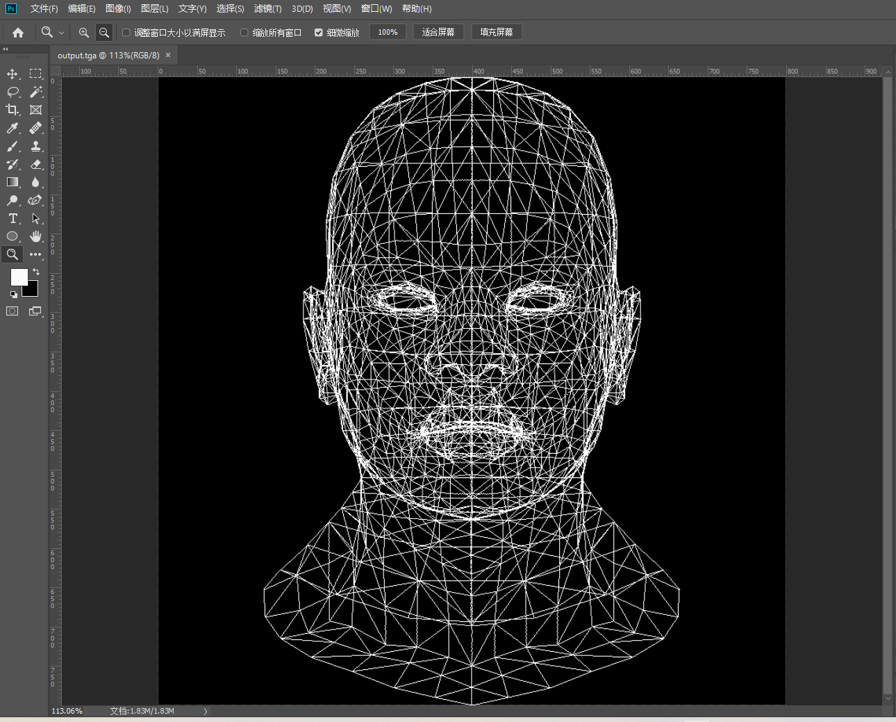
下面我们使用项目提供的文件来绘制人脸,在使用obj文件之前,我们还需要其他项目文件,例如几何处理等,这里我们并不关心其内部是如何实现的
最后产生的图片是
Lesson 2、三角形栅格化和背面剔除
经过上一节的探讨,现在我们已经可以绘制两个点之间的一条线段,现在我们需要绘制一个三角形,这很简单,绘制三条线段,首尾相连即可。
void triangle(Vec2i t0, Vec2i t1, Vec2i t2, TGAImage& image, TGAColor Color) { line(t0, t1, image, Color); line(t1, t2, image, Color); line(t2, t0, image, Color); } Vec2i t0[3] = { Vec2i(10, 70), Vec2i(50, 160), Vec2i(70, 80) }; Vec2i t1[3] = { Vec2i(180, 50), Vec2i(150, 1), Vec2i(70, 180) }; Vec2i t2[3] = { Vec2i(180, 150), Vec2i(120, 160), Vec2i(130, 180) }; triangle(t0[0], t0[1], t0[2], image, red); triangle(t1[0], t1[1], t1[2], image, white); triangle(t2[0], t2[1], t2[2], image, green);- 1
- 2
- 3
- 4
- 5
- 6
- 7
- 8
- 9
- 10
- 11
- 12
- 13
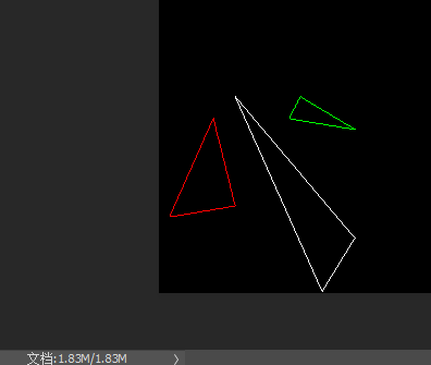
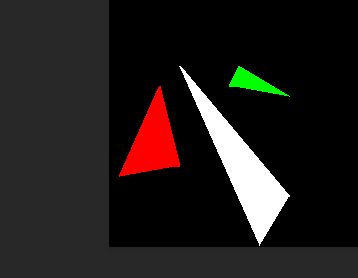
很好,现在我们已经可以绘制出三角形了,但是我们还需要进行栅格化,也就是把三角形进行填充,相信有了前面的经验,这里也能很快想到办法,就是扫线法。按照教程,我们需要把三角形分成两个部分来绘制,这样就需要对三角形的点进行预处理,t0>t1>t2,从t1顶点划水平线来分割三角形
void triangle(Vec2i t0, Vec2i t1, Vec2i t2, TGAImage& image, TGAColor Color) { if (t0.y > t1.y) std::swap(t0, t1); if (t0.y > t2.y) std::swap(t0, t2); if (t1.y > t2.y) std::swap(t1, t2); int total_height = t2.y - t0.y; for (int y = t0.y;y <= t1.y; y++) { int segment_height = t1.y - t0.y+1; float alpha = (float)(y - t0.y) / total_height; float beta = (float)(y - t0.y) / segment_height; Vec2i A = t0 + (t2 - t0) * alpha; Vec2i B = t0 + (t1 - t0) * beta; if (A.x > B.x)std::swap(A, B); for (int x = A.x;x <= B.x; x++) { image.set(x, y, Color); } } for (int y = t1.y; y <= t2.y; y++) { int segment_height = t2.y - t1.y + 1; float alpha = (float)(y - t0.y) / total_height; float beta = (float)(y - t1.y) / segment_height; Vec2i A = t0 + (t2 - t0) * alpha; Vec2i B = t1 + (t2 - t1) * beta; if (A.x > B.x)std::swap(A, B); for (int x = A.x; x <= B.x; x++) { image.set(x, y, Color); } } }- 1
- 2
- 3
- 4
- 5
- 6
- 7
- 8
- 9
- 10
- 11
- 12
- 13
- 14
- 15
- 16
- 17
- 18
- 19
- 20
- 21
- 22
- 23
- 24
- 25
- 26
- 27
- 28
- 29
- 30
- 31
- 32
- 33
这段代码就可以对一个三角形进行栅格化填充,将三角形分成两个部分,分别使用扫线法进行填充。
void triangle(Vec2i t0, Vec2i t1, Vec2i t2, TGAImage& image, TGAColor Color) { if (t0.y > t1.y) std::swap(t0, t1); if (t0.y > t2.y) std::swap(t0, t2); if (t1.y > t2.y) std::swap(t1, t2); int total_height = t2.y - t0.y; for (int i = 0; i <= total_height; ++i) { bool second_half = i > t1.y - t0.y || t1.y == t0.y; int segment_height = (second_half ? t2.y - t1.y : t1.y - t0.y) + 1; float alpha = (float)i / total_height; float beta = (float)(second_half?i-(t1.y-t0.y):i) / segment_height; Vec2i A = t0 + (t2 - t0) * alpha; Vec2i B = second_half? t1 + (t2 - t1) * beta: t0 + (t1 - t0) * beta; if (A.x > B.x)std::swap(A, B); for (int x = A.x; x <= B.x; x++) { image.set(x, i+t0.y, Color); } } }- 1
- 2
- 3
- 4
- 5
- 6
- 7
- 8
- 9
- 10
- 11
- 12
- 13
- 14
- 15
- 16
- 17
- 18
- 19
- 20
- 21
上面的代码是对原始的三角形栅格化代码进行了整理,原来的代码有大量的重复的部分,改进的代码使用了标志变量,让代码更加简洁。至此,我们已经可以绘制出线段、三角形,并可以填充三角形了。上面的填充三角形的办法有点古老,尽管其是准确的,下面我们将会探讨其他的填充方法。
上面的代码是找到每一个在三角形内部的像素点,然后进行绘制,我们新的方法将会处理更多的像素点,包括一些不在三角形内部的点,对于现代计算机来说,多的这些点产生的额外的性能消耗可以忽略不计。具体方法是找到三角形的最小包围盒,包围盒就是能把三角形完全包含起来的矩形框,然后对包围盒里面的点进行判断,判断其是否在三角形内部,判断方法使用**重心坐标。**关于重心坐标可以查看百科,games101也有相关介绍。
//求重心坐标 Vec3f barycentric(Vec3f A, Vec3f B, Vec3f C, Vec3f P) { //利用叉积计算P点的重心坐标 Vec3f k = Vec3f(C.x - A.x, B.x - A.x, A.x - P.x) ^ Vec3f(C.y - A.y, B.y - A.y, A.y - P.y); //三点共线时 if (std::abs(k.z) <1) return Vec3f(-1, 1, 1); //返回归一化的重心坐标 return Vec3f(1.f - (k.x + k.y) / k.z, k.x / k.z, k.y / k.z); }- 1
- 2
- 3
- 4
- 5
- 6
- 7
- 8
- 9
- 10
- 11
void triangle(Vec3f* pts, TGAImage& image, TGAColor color) { //声明包围盒,并给予初始值 Vec2f bboxmin(std::numeric_limits::max(), std::numeric_limits ::max()); Vec2f bboxmax(-std::numeric_limits ::max(), -std::numeric_limits ::max()); Vec2f clamp(image.get_width() - 1, image.get_height() - 1); for (int i = 0; i < 3; ++i) { //确定包围盒 bboxmin.x = std::max(.0f, std::min(bboxmin.x, pts[i].x)); bboxmin.y = std::max(.0f, std::min(bboxmin.y, pts[i].y)); //第一个max和min只是为了确保包围盒的合法性 bboxmax.x = std::min(clamp.x, std::max(bboxmax.x, pts[i].x)); bboxmax.y = std::min(clamp.y, std::max(bboxmax.y, pts[i].y)); } Vec3f p;//临时储存包围盒里的每一个像素坐标 for (p.x = bboxmin.x; p.x <= bboxmax.x; p.x++) { for (p.y = bboxmin.y; p.y <= bboxmax.y; p.y++) { //遍历包围盒 //获取P的重心坐标 Vec3f u = barycentric(pts[0], pts[1], pts[2], p); //判断是否在三角形内,不在就不做操作,在就将其像素染色 if (u.x < 0 || u.y < 0 || u.z < 0) continue; image.set(p.x, p.y, color); } } } - 1
- 2
- 3
- 4
- 5
- 6
- 7
- 8
- 9
- 10
- 11
- 12
- 13
- 14
- 15
- 16
- 17
- 18
- 19
- 20
- 21
- 22
- 23
- 24
- 25
- 26
- 27
- 28
- 29
最后效果如下:

在上一节我们已经能够利用obj文件来绘制三角形网格模型,这节我们又学习了三角形的填充,所以现在对上一节的网格模型进行填充
for (int i = 0; i < model->nfaces(); i++) { std::vectorface = model->face(i); Vec2f screen_coords[3];//屏幕坐标 for (int j = 0; j < 3; ++j) { Vec3f v = model->vert(face[j]);//世界坐标 screen_coords[j] = Vec2f((v.x + 1.) * width / 2., (v.y + 1.) * height / 2.); } triangle(screen_coords, image, TGAColor(rand() % 255, rand() % 255, rand() % 255, 255)); } - 1
- 2
- 3
- 4
- 5
- 6
- 7
- 8
- 9
- 10
- 11
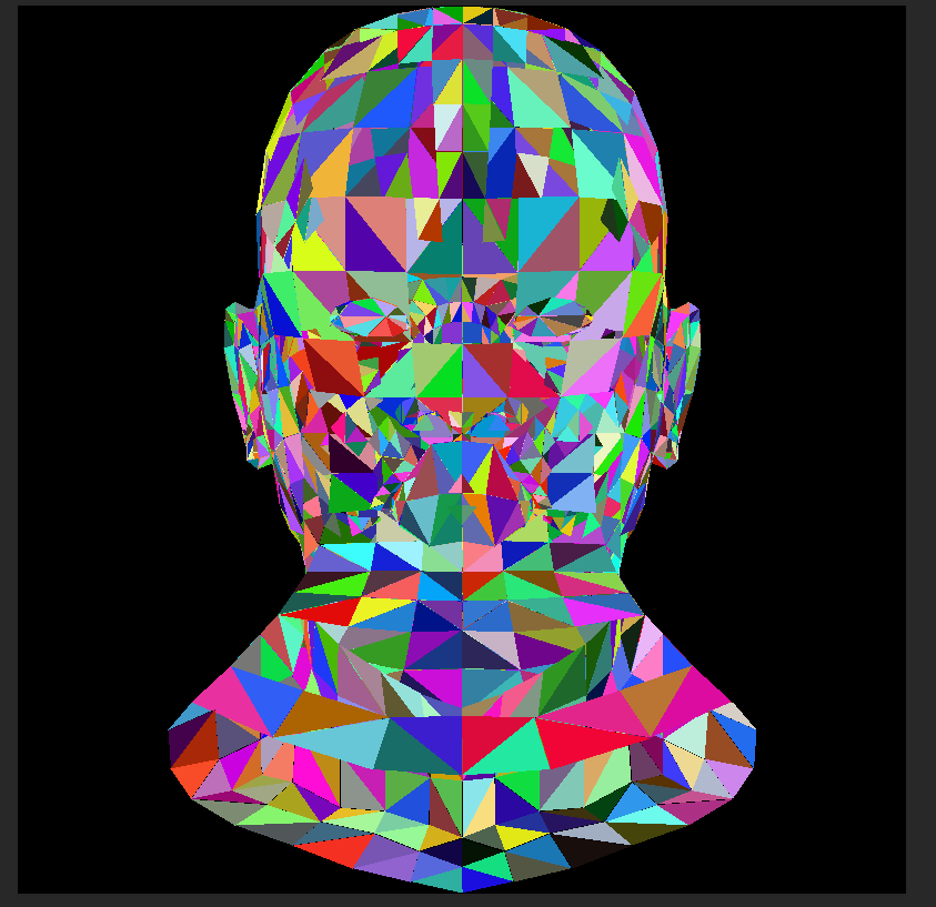
看起来比单纯的网格模型要绚烂许多了,但是面部细节没有,接下来我们需要根据简单的光照原理来进行绘制。我们可以知道的是,光照射到平面上,平面接受的光越多,根据能量守恒定律,光强越小,光越暗,这里我们使用理想的平行光源,不考虑光的衰减,那么平面反射的光就只和平面被照射到的面积有关,而被照射到的面积又与平面和平行光的夹角有关,要知道夹角,就要知道三角形平面的法向量。
至此,我们找到了展现阴影的关键,就是要计算平面的法向量,然后用法向量和光源相乘,就能得到相应的光强。不同的光强就能展示出阴影的效果。
Vec3f light_dir(0, 0, -1); for (int i = 0; i < model->nfaces(); i++) { std::vectorface = model->face(i); Vec2i screen_coords[3];//屏幕坐标 Vec3f world_coords[3];//世界坐标 for (int j = 0; j < 3; ++j) { Vec3f v = model->vert(face[j]); screen_coords[j] = Vec2i((v.x + 1.) * width / 2., (v.y + 1.) * height / 2.); world_coords[j] = v; } //使用世界坐标来计算法向量 Vec3f n = (world_coords[2] - world_coords[0]) ^ (world_coords[1] - world_coords[0]); n.normalize(); //计算光照强度,即法向量乘以光照方向 float intensity = n*light_dir; //光照强度大于0才能被检测到,小于0的是在背光面,观察不到,不用绘制,即背部剔除 if (intensity > 0) { triangle(screen_coords, image, TGAColor(intensity * 255, intensity * 255, intensity * 255, 255)); } } - 1
- 2
- 3
- 4
- 5
- 6
- 7
- 8
- 9
- 10
- 11
- 12
- 13
- 14
- 15
- 16
- 17
- 18
- 19
- 20
- 21
- 22
- 23
- 24
- 25
- 26
- 27
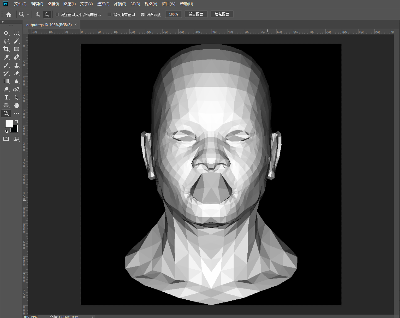
好,到这里我们此次课程的前两课就结束喽,后面的课程会以两节为一次来学习。 -
相关阅读:
深入了解 Docker 容器操作命令:掌握容器化管理的关键
Lit(六):内置指令、自定义指令
操作系统期末复习整理知识点
mysql 计算两个坐标距离
一个软件打磨了24年,被安装超过100亿次,居然赚不到钱?
排序算法——直接插入排序
p4v搭建UE4引擎,没弄好导致运行项目老出问题
【计算机网络】网络层——IP协议
JavaScript篇
Kubernetes学习笔记
- 原文地址:https://blog.csdn.net/qq_51599283/article/details/126324338
