-
OCCT示例学习笔记3--Modeling项目
OCCT的版本是7.6.0. Modeling项目,代码学习记录。
OCCT示例学习笔记3--Modeling项目
- 1、点镜像
- 2、轴镜像
- 3、旋转效果
- 4、缩放效果
- 5、移动效果
- 6、轴坐标位移效果
- 7、移动效果
- 8、各种基础模型显示
- 9、各种元素的旋转建模
- 10、pipe的建模
- 11、thru的建模
- 12、进化形状的建模
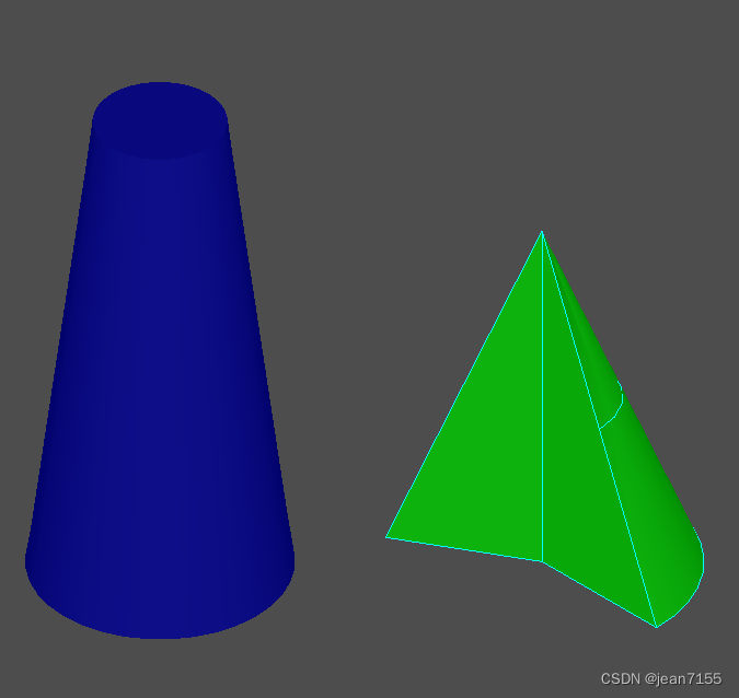
- 13、锥形变换
- 14、布尔运算
- 15、截面运算
- 16、平面的截面运算
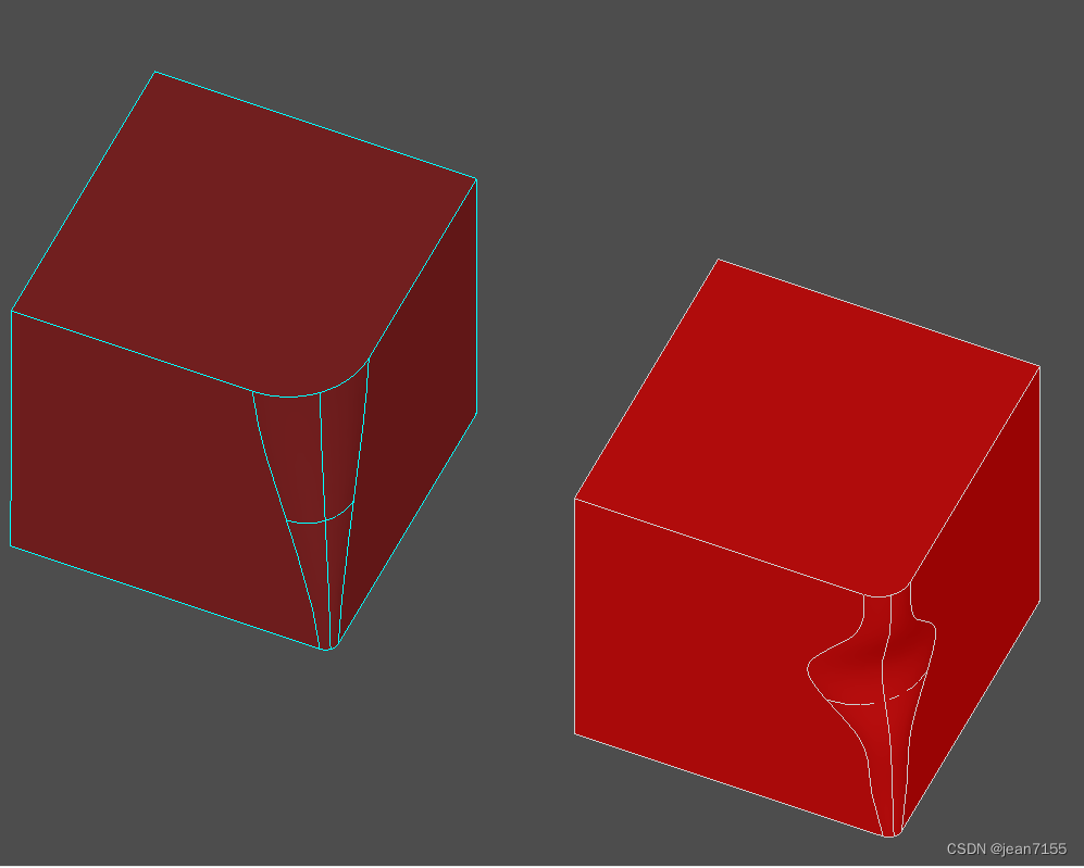
- 17、倒角运算
- 18、复杂倒角的建模
- 19、倒直角的建模
- 20、草图拉伸
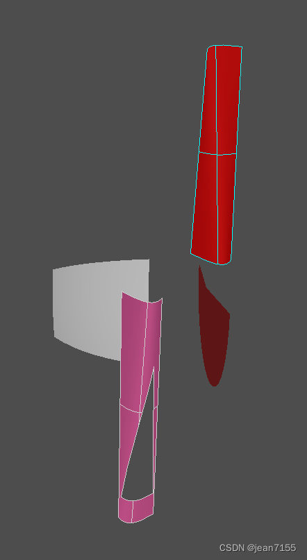
- 21、拔模棱镜的建模
- 22、旋转的建模
- 23、管道的建模
- 24、肋或凹槽的建模
- 25、局部粘合的建模
- 26、局部切割的建模
- 27、局部抽壳的建模
- 28、偏移的建模
- 29、vertex的建模
- 30、edge的建模
- 31、wire的建模
- 32、Face的建模
- 33、Shell的建模
- 34、Compound的建模
- 35、缝合的建模
- 36、手动的建模
- 37、基本几何建模
- 38、子图形显示
- 39、检查形状是否“正确”
- 40、曲线长度、质心和惯性矩阵
- 41、曲面的面积、质心和惯性矩阵
- 42、实体的体积、质心和惯性矩阵
- 43、edge修补建模(有点难懂。暂时略)
- 44、OnFillwithtang建模(有点难懂。暂时略)
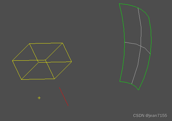
1、点镜像
在void CModelingDoc::OnMirror() 函数中。
显示效果如下:

应用的类如下:- BRepPrimAPI_MakeWedge类;上图显示的绿色梯形
- Geom_CartesianPoint类;点Geom_Point的实现类。
- AIS_Point类,显示点的类,上图中间的黄色十字。
- gp_Trsf类,设置镜像移动。
- BRepBuilderAPI_Transform类;移动变换。
2、轴镜像
在void CModelingDoc::OnMirroraxis()函数中。
显示效果如下:

应用的类如下:- gp_Ax1类,描述轴的类
- Geom_Axis1Placement类;描述 3D 空间中的轴。
- AIS_Axis类,显示轴的类。
3、旋转效果
在void CModelingDoc::OnRotate()函数中。
显示效果如下:

应用的类如下:
上面都有了。略4、缩放效果
在void CModelingDoc::OnScale()函数中。
显示效果如下:

应用的类如下:
上面都有了。略5、移动效果
在void CModelingDoc::OnTranslation()函数中。
显示效果如下:

应用的类如下:
ISession_Direction类,AIS_InteractiveObject类的子类,显示移动轴。6、轴坐标位移效果
在void CModelingDoc::OnDisplacement()函数中。
显示效果如下:

应用的类如下:
通过设置轴来设置位移效果。gp_Ax3 ax3_1(gp_Pnt(0,0,0),gp_Dir(0,0,1)); gp_Ax3 ax3_2(gp_Pnt(60,60,60),gp_Dir(1,1,1)); gp_Trsf theTransformation; theTransformation.SetDisplacement(ax3_1, ax3_2);- 1
- 2
- 3
- 4
7、移动效果
在void CModelingDoc::OnDeform()函数中。
显示效果如下:

应用的类如下:
- BRepBuilderAPI_GTransform类
- gp_GTrsf类,定义 3D 空间中的非持久变换
- gp_Mat类
gp_GTrsf theTransformation; gp_Mat rot(5, 0, 0, 0, 3, 0, 0, 0, 1); theTransformation.SetTranslationPart(gp_XYZ(5, 5, 5));//平移和缩放的位置前后没有变换 theTransformation.SetVectorialPart(rot);//这个是不同轴向的缩放- 1
- 2
- 3
- 4
8、各种基础模型显示
在void CModelingDoc::OnBox() 函数中。显示效果如下:

在void CModelingDoc::OnCylinder() 函数中。显示效果如下:

在void CModelingDoc::OnCone() 函数中。显示效果如下:
在void CModelingDoc::OnSphere()函数中。显示效果如下:

在CModelingDoc::OnTorus()函数中。显示效果如下:

在CModelingDoc::OnWedge()函数中。显示效果如下:

在CModelingDoc::OnPrism()函数中。显示效果如下:(拉伸功能)

应用的类如下:
- BRepPrimAPI_MakeBox类
- BRepPrimAPI_MakeCylinder类
- BRepPrimAPI_MakeCone类
- BRepPrimAPI_MakeSphere类
- BRepPrimAPI_MakeTorus类
- BRepPrimAPI_MakeWedge类
- BRepPrimAPI_MakePrism
- BRepBuilderAPI_MakeVertex
- BRepBuilderAPI_MakeEdge
- BRepBuilderAPI_MakeWire
- BRepBuilderAPI_MakeFace
- BRepPrimAPI_MakePrism
9、各种元素的旋转建模
在void CModelingDoc::OnRevol()函数中。显示效果如下:

应用的类如下:- BRepPrimAPI_MakeRevol类,制作旋转扫描拓扑的类。
- Geom_Axis1Placement类,描述 3D 空间中的轴。
- AIS_Axis类,显示 3D 空间中的轴。
10、pipe的建模
在void CModelingDoc::OnPipe()函数中。显示效果如下:


应用的类如下:- TColgp_Array1OfPnt类,是gp_Pnt 的容器。
- gp_Pnt类,三维描述一个点。
- Geom_BezierCurve类,描述有理或非有理贝塞尔曲线。(不懂)
- gp_Circ类,描述三维的一个圆。
- BRepOffsetAPI_MakePipe类,描述构建管道的函数。管道通过扫掠沿线(称为脊柱)构建基本形状(称为轮廓)。轮廓不得包含实体。
主要代码如下:
TopoDS_Edge E = BRepBuilderAPI_MakeEdge(curve); TopoDS_Wire wire = BRepBuilderAPI_MakeWire(E); gp_Circ c = gp_Circ(gp_Ax2(gp_Pnt(0.,0.,0.),gp_Dir(0.,1.,0.)),10.); TopoDS_Edge Ec = BRepBuilderAPI_MakeEdge(c); TopoDS_Wire Wc = BRepBuilderAPI_MakeWire(Ec); TopoDS_Face F = BRepBuilderAPI_MakeFace(gp_Pln(gp::ZOX()),Wc); TopoDS_Shape S = BRepOffsetAPI_MakePipe(wire,F);- 1
- 2
- 3
- 4
- 5
- 6
- 7
- 8
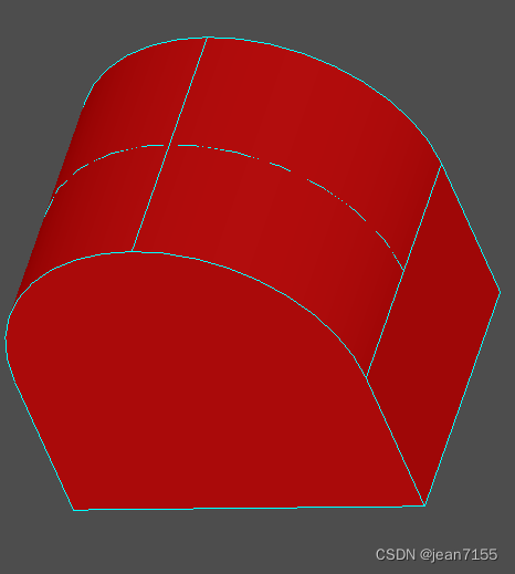
11、thru的建模
在void CModelingDoc::OnThru()函数中。显示效果如下:

应用的类如下:
- BRepOffsetAPI_ThruSections类,这是一个壳或实体以给定的顺序通过一组部分。通常部分是连线,但第一个和最后一个部分可能是顶点。上图就是该类的两个创建效果一个是平滑化的建模。
主要代码如下:
BRepOffsetAPI_ThruSections generator(Standard_False,Standard_True); generator.AddWire(W1); generator.AddWire(W3); generator.AddWire(W4); generator.AddWire(W2); generator.Build(); TopoDS_Shape S1 = generator.Shape();- 1
- 2
- 3
- 4
- 5
- 6
- 7
12、进化形状的建模
在void CModelingDoc::OnEvolved()函数中。显示效果如下:


GeomAbs_Arc类型的效果图。
应用的类如下:
- BRepBuilderAPI_MakePolygon类,描述构建多边形线的函数。
- BRepOffsetAPI_MakeEvolved类,描述构建进化形状的函数。演化的形状由平面脊(面或线)和轮廓(线)构建而成。
主要代码如下:
BRepBuilderAPI_MakePolygon P; P.Add(gp_Pnt(0.,0.,0.)); P.Add(gp_Pnt(200.,0.,0.)); P.Add(gp_Pnt(200.,200.,0.)); P.Add(gp_Pnt(0.,200.,0.)); P.Add(gp_Pnt(0.,0.,0.)); TopoDS_Wire W = P.Wire(); TopoDS_Wire wprof = BRepBuilderAPI_MakePolygon( gp_Pnt(0.,0.,0.),gp_Pnt(-60.,-60.,-200.)); TopoDS_Shape S = BRepOffsetAPI_MakeEvolved( W,wprof,GeomAbs_Arc,Standard_True,Standard_False, Standard_True,0.0001); Handle(AIS_Shape) ais3 = new AIS_Shape(wprof); myAISContext->Display(ais3,Standard_False);- 1
- 2
- 3
- 4
- 5
- 6
- 7
- 8
- 9
- 10
- 11
- 12
- 13
- 14
- 15
- 16
13、锥形变换
在void CModelingDoc::OnDraft()函数中。显示效果如下:

应用的类如下:- BRepOffsetAPI_DraftAngle类,形状上的锥形添加变换。
主要代码如下:
BRepOffsetAPI_DraftAngle adraft(S); int i =1; TopExp_Explorer Ex; for (Ex.Init(S,TopAbs_FACE); Ex.More(); Ex.Next()) { TopoDS_Face F = TopoDS::Face(Ex.Current()); Handle(Geom_Plane) surf = Handle(Geom_Plane)::DownCast(BRep_Tool::Surface(F)); gp_Pln apln = surf->Pln(); gp_Dir dirF = apln.Axis().Direction(); if (dirF.IsNormal(gp_Dir(0.,0.,1.),Precision::Angular())) adraft.Add(F, gp_Dir(0.,0.,1.), 15.0*M_PI/180, gp_Pln(gp::XOY())); } ais1->Set(adraft.Shape()); myAISContext->Redisplay(ais1,Standard_False);- 1
- 2
- 3
- 4
- 5
- 6
- 7
- 8
- 9
- 10
- 11
- 12
- 13
14、布尔运算
在void CModelingDoc::OnCut()函数中。显示效果如下:

在void CModelingDoc::OnFuse()函数中。显示效果如下:

在void CModelingDoc::OnCommon()函数中。显示效果如下:

应用的类如下:
- BRepAlgoAPI_Cut类,布尔减运算。
- BRepAlgoAPI_Fuse类,布尔加运算。
- BRepAlgoAPI_Common类,布尔交集运算。
主要代码如下:
TopoDS_Shape FusedShape = BRepAlgoAPI_Fuse(theBox1, theBox2); TopoDS_Shape ShapeCut = BRepAlgoAPI_Cut(theSphere, theBox); TopoDS_Shape theCommonSurface = BRepAlgoAPI_Common(theBox, theWedge);- 1
- 2
- 3
15、截面运算
在void CModelingDoc::OnSection()函数中。显示效果如下:

应用的类如下:
- BRepPrimAPI_MakeTorus类,构建圆环形状类。
- BRepPrimAPI_MakeSphere类,构建球体形状类。
- BRepAlgoAPI_Section类,是在参数和工具之间建立一个截面算法。Section运算的结果由顶点和边组成。
主要代码如下:
BRepAlgoAPI_Section section(atorus, asphere, PerformNow); section.ComputePCurveOn1(Standard_True); section.Approximation(TopOpeBRepTool_APPROX); section.Build(); Handle(AIS_Shape) asection = new AIS_Shape(section.Shape()); myAISContext->SetDisplayMode(asection, 0, Standard_False);- 1
- 2
- 3
- 4
- 5
- 6
- 7
16、平面的截面运算
在void CModelingDoc::OnPsection()函数中。显示效果如下:

应用的类如下:
- gp_Pln类,描述 3D 空间中的平面。
- Geom_Plane类,描述 3D 空间中的平面。
- gce_MakePln类,实现了以下用于从 gp 创建平面的算法。
- gp_Pln类,Geom_Plane类和gce_MakePln类,都是描述三维空间中的平面,他们是不同包中的不同算法,每个类里面有一些不同的算法。
- AIS_Plane类,构造用于显示复合形状的平面基准。
- BRepAlgoAPI_Section类,是在参数和工具之间建立一个截面算法。Section运算的结果由顶点和边组成。
主要代码如下:
BRepAlgoAPI_Section section(atorus, asphere, PerformNow); section.ComputePCurveOn1(Standard_True); section.Approximation(TopOpeBRepTool_APPROX); section.Build(); Handle(AIS_Shape) asection = new AIS_Shape(section.Shape()); myAISContext->SetDisplayMode(asection, 0, Standard_False);- 1
- 2
- 3
- 4
- 5
- 6
- 7
17、倒角运算
在void CModelingDoc::OnBlend()函数中。显示效果如下:

应用的类如下:
- BRepFilletAPI_MakeFillet类,倒角运算。
- TopExp_Explorer类,遍历模型中面、线、边和点的类。
- TopoDS类,类型转换类。
- BRepAlgoAPI_Fuse类,布尔加类。
主要代码如下:
BRepFilletAPI_MakeFillet fillet(Box); for (TopExp_Explorer ex(Box, TopAbs_EDGE); ex.More(); ex.Next()) { TopoDS_Edge Edge = TopoDS::Edge(ex.Current()); fillet.Add(20, Edge); } TopoDS_Shape blendedBox = fillet.Shape();- 1
- 2
- 3
- 4
- 5
- 6
- 7
- 8
18、复杂倒角的建模
在void CModelingDoc::OnEvolvedblend()函数中。显示效果如下:

应用的类如下:
- BRepFilletAPI_MakeFillet类,add函数的多态使用。用不同的算法。
主要代码如下:
BRepFilletAPI_MakeFillet afillet(theBox2); TColgp_Array1OfPnt2d TabPoint(1, 6); gp_Pnt2d P1(0., 8.); gp_Pnt2d P2(0.2, 16.); gp_Pnt2d P3(0.4, 25.); gp_Pnt2d P4(0.6, 55.); gp_Pnt2d P5(0.8, 28.); gp_Pnt2d P6(1., 20.); TabPoint.SetValue(1, P1); TabPoint.SetValue(2, P2); TabPoint.SetValue(3, P3); TabPoint.SetValue(4, P4); TabPoint.SetValue(5, P5); TabPoint.SetValue(6, P6); TopExp_Explorer exp(theBox2, TopAbs_EDGE); exp.Next(); exp.Next(); exp.Next(); exp.Next(); afillet.Add(TabPoint, TopoDS::Edge(exp.Current())); afillet.Build(); if (afillet.IsDone()) TopoDS_Shape LawevolvedBox = afillet.Shape();- 1
- 2
- 3
- 4
- 5
- 6
- 7
- 8
- 9
- 10
- 11
- 12
- 13
- 14
- 15
- 16
- 17
- 18
- 19
- 20
- 21
- 22
- 23
- 24
- 25
- 26
- 27
19、倒直角的建模
在void CModelingDoc::OnChamf()函数中。显示效果如下:

应用的类如下:
- BRepFilletAPI_MakeChamfer类,倒直角运算。
主要代码如下:
BRepFilletAPI_MakeChamfer MC(theBox); // add all the edges to chamfer TopTools_IndexedDataMapOfShapeListOfShape M; TopExp::MapShapesAndAncestors(theBox, TopAbs_EDGE, TopAbs_FACE, M); for (Standard_Integer i = 1; i <= M.Extent(); i++) { TopoDS_Edge E = TopoDS::Edge(M.FindKey(i)); TopoDS_Face F = TopoDS::Face(M.FindFromIndex(i).First()); MC.Add(5, 5, E, F); } TopoDS_Shape ChanfrenedBox = MC.Shape();- 1
- 2
- 3
- 4
- 5
- 6
- 7
- 8
- 9
- 10
- 11
- 12
20、草图拉伸
在void CModelingDoc::OnPrismLocal()函数中。显示效果如下:

应用的类如下:
- BRepAlgoAPI_Cut类,布尔减运算
- gp_Pnt2d类,GCE2d_MakeLine类,Geom2d_Curve类
- BRepBuilderAPI_MakeEdge 类,应用的是
- BRepLib::BuildCurves3d()函数。
- BRepFeat_MakePrism类,拉伸命令。
主要代码如下:
TopoDS_Face FP2; { gp_Pnt2d p1 = gp_Pnt2d(100., 100.); gp_Pnt2d p2 = gp_Pnt2d(200., 100.); gp_Pnt2d p3 = gp_Pnt2d(150., 200.); Handle(Geom2d_Curve) aline1 = GCE2d_MakeLine(p1, p2).Value(); Handle(Geom2d_Curve) aline2 = GCE2d_MakeLine(p2, p3).Value(); Handle(Geom2d_Curve) aline3 = GCE2d_MakeLine(p3, p1).Value(); TopoDS_Edge e1 = BRepBuilderAPI_MakeEdge(aline1, surf, 0., p1.Distance(p2)); TopoDS_Edge e2 = BRepBuilderAPI_MakeEdge(aline2, surf, 0., p2.Distance(p3)); TopoDS_Edge e3 = BRepBuilderAPI_MakeEdge(aline3, surf, 0., p3.Distance(p1)); BRepBuilderAPI_MakeWire MW2; MW2.Add(e1); MW2.Add(e2); MW2.Add(e3); TopoDS_Wire wire3E = MW2.Wire(); BRepBuilderAPI_MakeFace MKF2; MKF2.Init(surf, Standard_False, Precision::Confusion()); MKF2.Add(wire3E); FP2 = MKF2.Face(); BRepLib::BuildCurves3d(FP2);//计算的所有边的 3d 曲线} BRepFeat_MakePrism MKP2(res1, FP2, F2, D, 1, Standard_True); MKP2.Perform(100.); TopoDS_Shape res2 = MKP2.Shape(); ais1->Set(res2); myAISContext->Redisplay(ais1, Standard_False);//更新显示模型 myAISContext->SetSelected(anIO1, Standard_False);//设置为选中 Fit();- 1
- 2
- 3
- 4
- 5
- 6
- 7
- 8
- 9
- 10
- 11
- 12
- 13
- 14
- 15
- 16
- 17
- 18
- 19
- 20
- 21
- 22
- 23
- 24
- 25
- 26
- 27
- 28
- 29
- 30
- 31
- 32
- 33
具体代码分析:
const Handle(Geom_Surface)& S 参数指定了三维表面。
BRepBuilderAPI_MakeEdge是将二维的曲线(const Handle(Geom2d_Curve)& L)在指定三维平面上创建三维边。
比如上图中:草图是二维平面上的曲线。在某个指定平面上绘制草图,再进行拉伸操作。这里就是,在某个指定平面上通过二维曲线创建三维边。
这里创建的三维边没有对应的三维曲线,如果后续用到三维曲线,就需要**BRepLib::BuildCurves3d()**函数对最后的三维模型进行三维曲线的构建。BRepBuilderAPI_MakeFace类,也有类似的使用,见代码。
**Redisplay()**函数用于显示的时候更新模型,还有设置成选中状态。
21、拔模棱镜的建模
在void CModelingDoc::OnDprismLocal()函数中。显示效果如下:

应用的类如下:
- BRepFeat_MakeDPrism类,描述从基本形状表面构建拔模棱镜拓扑的函数。
- gp_Circ2d类和Geom2d_Curve类,二维曲线圆。
主要代码如下:
//描述从基本形状表面构建拔模棱镜拓扑的函数。 BRepFeat_MakeDPrism MKDP(S,FP,F,10*M_PI/180,1,Standard_True); MKDP.Perform(200); TopoDS_Shape res1 = MKDP.Shape();- 1
- 2
- 3
- 4
22、旋转的建模
在void CModelingDoc::OnRevolLocal()函数中。显示效果如下:

应用的类如下:
- BRepFeat_MakeRevol类,描述从基本形状构建旋转壳的函数。
主要代码如下:
BRepFeat_MakeRevol MKrev(S,FP,F1, gp::OX(),1,Standard_True);//描述从基本形状构建旋转壳的函数 //。。。 TopoDS_Face F2 = TopoDS::Face(Ex.Current()); MKrev.Perform(F2); TopoDS_Shape res1 = MKrev.Shape();- 1
- 2
- 3
- 4
- 5
23、管道的建模
在void CModelingDoc::OnPipeLocal()函数中。显示效果如下:

应用的类如下:
- BRepFeat_MakePipe类,构造具有管道特征的复合形状。
主要代码如下:
BRepFeat_MakePipe MKPipe(S,FP,F1,W,1,Standard_True); MKPipe.Perform(); TopoDS_Shape res1 = MKPipe.Shape(); ais1->Set(res1);- 1
- 2
- 3
- 4
24、肋或凹槽的建模
在void CModelingDoc::OnLinearLocal()函数中。显示效果如下:

应用的类如下:
- BRepFeat_MakeLinearForm类,沿着可展开的平面构建肋或凹槽。。
主要代码如下:
TopoDS_Wire W = BRepBuilderAPI_MakeWire(BRepBuilderAPI_MakeEdge(pt1,pt2)); gp_Pnt pt3(50., 45., 150.); gp_Dir dir(0,1,0); Handle(Geom_Plane) aplane = new Geom_Plane(pt3,dir); //沿着可展开的平面构建肋或凹槽。 BRepFeat_MakeLinearForm aform(S, W, aplane, gp_Vec(0.,10.,0.), gp_Vec(0.,0.,0.), 1, Standard_True); aform.Perform(/*10.*/); // new in 2.0 TopoDS_Shape res = aform.Shape();- 1
- 2
- 3
- 4
- 5
- 6
- 7
- 8
- 9
- 10
- 11
- 12
- 13
25、局部粘合的建模
在void CModelingDoc::OnGlueLocal()函数中。显示效果如下:

应用的类如下:
- BRepFeat_Gluer类,用于局部粘合。Package BRepFeat包中的类。
这个类最重要的功能是使用本地操作而不是全局操作。在本地操作中,您可以使用正在创建特征的形状的各个方面来指定特征构造的域。这些语义是根据基础形状的成员形状来表达的,从该形状中添加或删除物质。
主要代码如下:
//如图左边的模型,只有face重合 TopoDS_Face F2 = TopoDS::Face(Ex2.Current()); BRepFeat_Gluer glue(S2,S1);//粘合的shape glue.Bind(F2,F1);//粘合的face TopoDS_Shape res1 = glue.Shape();- 1
- 2
- 3
- 4
- 5
//如图右边的模型,有face重合,而且face里面有边重合。 BRepFeat_Gluer glue2(S4,S3); glue2.Bind(F4,F3); LocOpe_FindEdges CommonEdges(F4,F3); for (CommonEdges.InitIterator(); CommonEdges.More(); CommonEdges.Next()) glue2.Bind(CommonEdges.EdgeFrom(),CommonEdges.EdgeTo()); TopoDS_Shape res2 = glue2.Shape();- 1
- 2
- 3
- 4
- 5
- 6
- 7
26、局部切割的建模
在void CModelingDoc::OnSplitLocal()函数中。显示效果如下:

应用的类如下:
- BRepAlgoAPI_Section类,切割,获得界面的edge。
- BRepFeat_SplitShape类,基准形状中面的线或边,用作特征的一部分,用于切割并投影到基础形状外部或内部的平面。通过重建结合工具的边缘和面的初始形状,可以构造突起或凹陷特征。
主要代码如下:
BRepAlgoAPI_Section asect(S, gp_Pln(1,2,1,-15),Standard_False); asect.ComputePCurveOn1(Standard_True); asect.Approximation(Standard_True); asect.Build(); TopoDS_Shape R = asect.Shape(); BRepFeat_SplitShape asplit(S); for (TopExp_Explorer Ex(R,TopAbs_EDGE); Ex.More(); Ex.Next()) { TopoDS_Shape anEdge = Ex.Current(); TopoDS_Shape aFace; if (asect.HasAncestorFaceOn1(anEdge,aFace)) //获得切割边anEdge所在的face。 { TopoDS_Face F = TopoDS::Face(aFace); TopoDS_Edge E = TopoDS::Edge(anEdge); asplit.Add(E,F); } } asplit.Build(); TopoDS_Shape Result = asplit.Shape();- 1
- 2
- 3
- 4
- 5
- 6
- 7
- 8
- 9
- 10
- 11
- 12
- 13
- 14
- 15
- 16
- 17
- 18
- 19
- 20
- 21
27、局部抽壳的建模
在void CModelingDoc::OnThickLocal()函数中。显示效果如下:
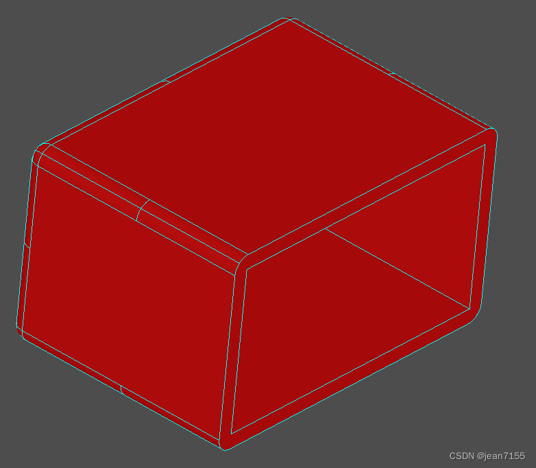
应用的类如下:
- BRepOffsetAPI_MakeThickSolid类,描述构建空心实体的函数。
主要代码如下:
BRepOffsetAPI_MakeThickSolid aSolidMaker; aSolidMaker.MakeThickSolidByJoin(S1,aList,10,0.01); TopoDS_Shape aThickSolid = aSolidMaker.Shape();- 1
- 2
- 3
28、偏移的建模
在void CModelingDoc::OnOffsetLocal()函数中。显示效果如下:

应用的类如下:
- BRepOffsetAPI_MakeOffsetShape类,描述用形状构建壳的函数。
主要代码如下:
//左边的模型 BRepOffsetAPI_MakeOffsetShape aShapeMaker1; aShapeMaker1.PerformByJoin(S1,40,0.01); TopoDS_Shape anOffsetShape1 = aShapeMaker1.Shape(); //右边的模型 BRepOffsetAPI_MakeOffsetShape aShapeMaker2; aShapeMaker2.PerformByJoin(S2,-40,0.01, BRepOffset_Skin,Standard_False,Standard_False,GeomAbs_Arc); TopoDS_Shape anOffsetShape2 = aShapeMaker2.Shape();- 1
- 2
- 3
- 4
- 5
- 6
- 7
- 8
- 9
- 10
29、vertex的建模
在void CModelingDoc::OnVertex()函数中。显示效果如下:

应用的类如下:
- BRepBuilderAPI_MakeVertex类,描述直接从 3D 几何点构建 BRepBuilder 顶点的函数。
主要代码如下:
TopoDS_Vertex V1,V2,V3; V1 = BRepBuilderAPI_MakeVertex(gp_Pnt(0,0,0)); V2 = BRepBuilderAPI_MakeVertex(gp_Pnt(10,7,25)); gp_Pnt P(-12,8,-4); BRepBuilderAPI_MakeVertex MV(P); V3 = MV.Vertex(); Handle(AIS_Shape) Point1 = new AIS_Shape(V1); myAISContext->Display(Point1,Standard_False);- 1
- 2
- 3
- 4
- 5
- 6
- 7
- 8
- 9
- 10
- 11
- 12
30、edge的建模
在void CModelingDoc::OnEdge()函数中。显示效果如下:

应用的类如下:
- BRepBuilderAPI_MakeEdge类,提供构建边缘的方法。
- gp_Lin类。
- gp_Elips类。
- Geom_BezierCurve类。
主要代码如下:
TopoDS_Edge BlueEdge,YellowEdge,WhiteEdge,RedEdge,GreenEdge; TopoDS_Vertex V1,V2,V3,V4; /The blue edge BlueEdge = BRepBuilderAPI_MakeEdge(gp_Pnt(-80,-50,-20),gp_Pnt(-30,-60,-60)); /The yellow edge V1 = BRepBuilderAPI_MakeVertex(gp_Pnt(-20,10,-30)); V2 = BRepBuilderAPI_MakeVertex(gp_Pnt(10,7,-25)); YellowEdge = BRepBuilderAPI_MakeEdge(V1,V2); /The white edge gp_Lin line(gp_Ax1(gp_Pnt(10,10,10),gp_Dir(1,0,0))); WhiteEdge = BRepBuilderAPI_MakeEdge(line,-20,10); //The red edge gp_Elips Elips(gp_Ax2(gp_Pnt(10,0,0),gp_Dir(1,1,1)),60,30); RedEdge = BRepBuilderAPI_MakeEdge(Elips,0,M_PI/2); /The green edge and the both extreme vertex gp_Pnt P1(-15,200,10); gp_Pnt P2(5,204,0); gp_Pnt P3(15,200,0); gp_Pnt P4(-15,20,15); gp_Pnt P5(-5,20,0); gp_Pnt P6(15,20,0); gp_Pnt P7(24,120,0); gp_Pnt P8(-24,120,12.5); TColgp_Array1OfPnt array(1,8); array.SetValue(1,P1); array.SetValue(2,P2); array.SetValue(3,P3); array.SetValue(4,P4); array.SetValue(5,P5); array.SetValue(6,P6); array.SetValue(7,P7); array.SetValue(8,P8); Handle (Geom_BezierCurve) curve = new Geom_BezierCurve(array); BRepBuilderAPI_MakeEdge ME (curve); GreenEdge = ME; V3 = ME.Vertex1(); V4 = ME.Vertex2();- 1
- 2
- 3
- 4
- 5
- 6
- 7
- 8
- 9
- 10
- 11
- 12
- 13
- 14
- 15
- 16
- 17
- 18
- 19
- 20
- 21
- 22
- 23
- 24
- 25
- 26
- 27
- 28
- 29
- 30
- 31
- 32
- 33
- 34
- 35
- 36
- 37
- 38
- 39
- 40
- 41
- 42
- 43
- 44
- 45
- 46
- 47
- 48
- 49
31、wire的建模
在void CModelingDoc::OnWire()函数中。显示效果如下:

应用的类如下:
- BRepBuilderAPI_MakeWire类。
- gp_Circ类
- gp_Elips类。
主要代码如下:
The red wire is build from a single edge gp_Elips Elips(gp_Ax2(gp_Pnt(250,0,0),gp_Dir(1,1,1)),160,90); Edge1 = BRepBuilderAPI_MakeEdge(Elips,0,M_PI/2); RedWire = BRepBuilderAPI_MakeWire(Edge1); ///the yellow wire is build from an existing wire and an edge gp_Circ circle(gp_Ax2(gp_Pnt(-300,0,0),gp_Dir(1,0,0)),80); Edge2 = BRepBuilderAPI_MakeEdge(circle,0,M_PI); ExistingWire = BRepBuilderAPI_MakeWire(Edge2); Edge3 = BRepBuilderAPI_MakeEdge(gp_Pnt(-300,0,-80),gp_Pnt(-90,20,-30)); BRepBuilderAPI_MakeWire MW1(ExistingWire,Edge3); if (MW1.IsDone()) { YellowWire = MW1; }- 1
- 2
- 3
- 4
- 5
- 6
- 7
- 8
- 9
- 10
- 11
- 12
- 13
- 14
- 15
- 16
- 17
- 18
- 19
- 20
BRepBuilderAPI_MakeWire MW; MW.Add(ExistingWire2); MW.Add(Edge5); MW.Add(Edge6); MW.Add(Edge7); if (MW.IsDone()) { WhiteWire = MW.Wire(); LastEdge = MW.Edge(); LastVertex = MW.Vertex(); }- 1
- 2
- 3
- 4
- 5
- 6
- 7
- 8
- 9
- 10
- 11
- 12
32、Face的建模
在void CModelingDoc::OnFace()函数中。显示效果如下:
应用的类如下:
- BRepBuilderAPI_MakeFace类。
- gp_Sphere类。
- GeomAPI_PointsToBSplineSurface类。
- Geom2d_Line类。
主要代码如下:
/ P1.SetCoord(35,-200,40); P2.SetCoord(50,-204,30); P3.SetCoord(65,-200,30); P4.SetCoord(35,-20,45); P5.SetCoord(45,-20,30); P6.SetCoord(65,-20,65); TColgp_Array2OfPnt array2(1,3,1,2); array2.SetValue(1,1,P1); array2.SetValue(2,1,P2); array2.SetValue(3,1,P3); array2.SetValue(1,2,P4); array2.SetValue(2,2,P5); array2.SetValue(3,2,P6); Handle (Geom_BSplineSurface) BSplineSurf = GeomAPI_PointsToBSplineSurface(array2,3,8,GeomAbs_C2,0.001); TopoDS_Face aFace = BRepBuilderAPI_MakeFace(BSplineSurf, Precision::Confusion()); //2d lines gp_Pnt2d P12d(0.9,0.1); gp_Pnt2d P22d(0.2,0.7); gp_Pnt2d P32d(0.02,0.1); Handle (Geom2d_Line) line1 = new Geom2d_Line(P12d,gp_Dir2d((0.2-0.9),(0.7-0.1))); Handle (Geom2d_Line) line2 = new Geom2d_Line(P22d,gp_Dir2d((0.02-0.2),(0.1-0.7))); Handle (Geom2d_Line) line3 = new Geom2d_Line(P32d,gp_Dir2d((0.9-0.02),(0.1-0.1))); //Edges are on the BSpline surface Edge1 = BRepBuilderAPI_MakeEdge(line1,BSplineSurf,0,P12d.Distance(P22d)); Edge2 = BRepBuilderAPI_MakeEdge(line2,BSplineSurf,0,P22d.Distance(P32d)); Edge3 = BRepBuilderAPI_MakeEdge(line3,BSplineSurf,0,P32d.Distance(P12d)); Wire1 = BRepBuilderAPI_MakeWire(Edge1,Edge2,Edge3); Wire1.Reverse(); PinkFace = BRepBuilderAPI_MakeFace(aFace,Wire1); BRepLib::BuildCurves3d(PinkFace);- 1
- 2
- 3
- 4
- 5
- 6
- 7
- 8
- 9
- 10
- 11
- 12
- 13
- 14
- 15
- 16
- 17
- 18
- 19
- 20
- 21
- 22
- 23
- 24
- 25
- 26
- 27
- 28
- 29
- 30
- 31
- 32
- 33
- 34
- 35
- 36
- 37
- 38
- 39
- 40
33、Shell的建模
在void CModelingDoc::OnShell()函数中。显示效果如下:

应用的类如下:
- Geom_BSplineSurface类。
- BRepBuilderAPI_MakeShell类。
主要代码如下:
34、Compound的建模
在void CModelingDoc::OnCompound()函数中。显示效果如下:
应用的类如下:
- TopoDS_Compound类。
- BRep_Builder类。
主要代码如下:
BRep_Builder builder; TopoDS_Compound Comp; builder.MakeCompound(Comp); TopoDS_Vertex aVertex = BRepBuilderAPI_MakeVertex(gp_Pnt(-20,10,-30)); builder.Add(Comp,aVertex); gp_Lin line(gp_Ax1(gp_Pnt(10,10,10),gp_Dir(1,0,0))); TopoDS_Edge anEdge = BRepBuilderAPI_MakeEdge(line,-20,10); builder.Add(Comp,anEdge); gp_Sphere sphere (gp_Ax3(gp_Pnt(-80,0,0),gp_Dir(1,0,0)),150); TopoDS_Face aFace = BRepBuilderAPI_MakeFace(sphere,0.1,0.7,0.2,0.9); builder.Add(Comp,aFace); TopoDS_Shape aBox = BRepPrimAPI_MakeBox(gp_Pnt(-60, 0, 0), 30, 60, 40).Shape(); builder.Add(Comp,aBox); Handle(AIS_Shape) white = new AIS_Shape(Comp); myAISContext->SetDisplayMode (white, 0, Standard_False); myAISContext->Display(white,Standard_False);- 1
- 2
- 3
- 4
- 5
- 6
- 7
- 8
- 9
- 10
- 11
- 12
- 13
- 14
- 15
- 16
- 17
- 18
- 19
- 20
- 21
- 22
35、缝合的建模
在void CModelingDoc::OnSewing()函数中。显示效果如下:

应用的类如下:
- BRepOffsetAPI_Sewing类,沿着它们的共同边缘缝合形状。
- Geom_Plane类,描述 3D 空间中的平面。
- Geom_RectangularTrimmedSurface类,描述由 u 参数方向上的两个 u 参数值和 v 参数方向上的两个 v 参数值限制的曲面部分(面片)。
- GeomAPI_PointsToBSplineSurface类,用于近似或内插通过点 Array2 的 BSplineSurface。
- Geom_BSplineSurface类,描述 BSpline 曲面。
主要代码如下:
BRepOffsetAPI_Sewing aMethod; aMethod.Add(FirstShape); aMethod.Add(SecondShape); aMethod.Perform(); TopoDS_Shape sewedShape = aMethod.SewedShape();- 1
- 2
- 3
- 4
- 5
36、手动的建模
在void CModelingDoc::OnBuilder()函数中。显示效果如下:
应用的类如下:
- BRep_Builder类,提供高级公差控制的框架。它用于构建形状。
- Geom_CylindricalSurface类。
- Geom2d_Line类。
- Geom2d_Circle类。
- Geom_Plane类。
这个示例是从Vertex到Edge,Edge到wire等顺序由代码建立的模型的拓扑结构。
主要代码如下:
TopoDS_Vertex V000, V001, V010, V011, V100, V101, V110, V111; B.MakeVertex(V000,gp_Pnt(0,0,0),precision); B.MakeVertex(V001,gp_Pnt(0,0,100),precision); B.MakeVertex(V010,gp_Pnt(0,150,0),precision); //。。。 TopoDS_Edge EX00, EX01, EX10, EX11; Handle (Geom_Line) L; //Edge X00 L = new Geom_Line(gp_Pnt(0,0,0),gp_Dir(1,0,0)); B.MakeEdge(EX00,L,precision); V000.Orientation(TopAbs_FORWARD); V100.Orientation(TopAbs_REVERSED); B.Add(EX00,V000); B.Add(EX00,V100); //Parameters B.UpdateVertex(V000,0,EX00,precision); B.UpdateVertex(V100,200,EX00,precision); //。。。 //Circular Edges Handle (Geom_Circle) C; //Standard_Real R = 100; //Edge EX01 C = new Geom_Circle(gp_Ax2(gp_Pnt(100,0,100),gp_Dir(0,1,0),gp_Dir(-1,0,0)),100); B.MakeEdge(EX01,C,precision); V001.Orientation(TopAbs_FORWARD); V101.Orientation(TopAbs_REVERSED); B.Add(EX01,V001); B.Add(EX01,V101); //Parameters B.UpdateVertex(V001,0,EX01,precision); B.UpdateVertex(V101,M_PI,EX01,precision);- 1
- 2
- 3
- 4
- 5
- 6
- 7
- 8
- 9
- 10
- 11
- 12
- 13
- 14
- 15
- 16
- 17
- 18
- 19
- 20
- 21
- 22
- 23
- 24
- 25
- 26
- 27
- 28
- 29
- 30
- 31
- 32
- 33
- 34
37、基本几何建模
在void CModelingDoc::OnGeometrie()函数中。显示效果如下:

就是点线面和线段4个几何模型的建立和显示。应用的类如下:
略。主要代码如下:
略。38、子图形显示
在void CModelingDoc::OnExplorer()函数中。显示效果如下:

应用的类如下:
- AIS_ColoredShape类,自定义指定子形状的属性。如果它不是主形状的子形状,该形状将被存储在地图中但被忽略。此方法可用于标记具有可自定义属性的子形状。
- AIS_ColoredDrawer类,可定制的属性。
- Prs3d_ShadingAspect 类,定义阴影显示的框架。
- AIS_ConnectedInteractive类,创建另一个交互对象的任意位置实例,用作参考。这允许您使用连接的交互式对象,而无需重新计算演示、选择或图形结构。这些是从您的参考对象推导出来的。连接的交互对象与其源之间的关系一般是一种几何变换。
- Geom_Transformation类,描述平移、旋转、缩放的基本变换。
主要代码如下:
这里做了一个动画效果,具体用每帧移动更新的效果实现的。//一个动画每帧位置的更新效果。 for (Standard_Integer i=1;i<=90;i++) { theMove->SetTranslation(move*i); if (orient==TopAbs_FORWARD) myAISContext->SetLocation(theTransformedDisplay,TopLoc_Location(theMove->Trsf())); else myAISContext->SetLocation(theTransformedDisplay,TopLoc_Location(theMove->Inverted()->Trsf())); myAISContext->Redisplay(theTransformedDisplay,true); }- 1
- 2
- 3
- 4
- 5
- 6
- 7
- 8
- 9
- 10
- 11
//Build an AIS_Shape with a new color Handle(AIS_Shape) theMovingFace = new AIS_Shape(aCurrentFace); Quantity_NameOfColor aCurrentColor = (Quantity_NameOfColor)j; myAISContext->SetColor(theMovingFace,aCurrentColor,Standard_False); myAISContext->SetMaterial(theMovingFace,Graphic3d_NOM_PLASTIC,Standard_False); //Find the normal vector of each face TopLoc_Location aLocation; Handle (AIS_ConnectedInteractive) theTransformedDisplay = new AIS_ConnectedInteractive(); theTransformedDisplay->Connect(theMovingFace, aLocation); Handle (Geom_Transformation) theMove = new Geom_Transformation(aLocation.Transformation()); myAISContext->Display(theTransformedDisplay,Standard_False); myAISContext->UpdateCurrentViewer(); Sleep (500);- 1
- 2
- 3
- 4
- 5
- 6
- 7
- 8
- 9
- 10
- 11
- 12
- 13
- 14
- 15
39、检查形状是否“正确”
在void CModelingDoc::OnValid()函数中。显示效果如下:

应用的类如下:
- BRepAlgo::IsValid()函数,检查形状是否“正确”。
主要代码如下:
Standard_Boolean theShapeIsValid = BRepAlgo::IsValid(S);//检查形状是否“正确”。- 1
40、曲线长度、质心和惯性矩阵
在void CModelingDoc::OnLinear()函数中。显示效果如下:
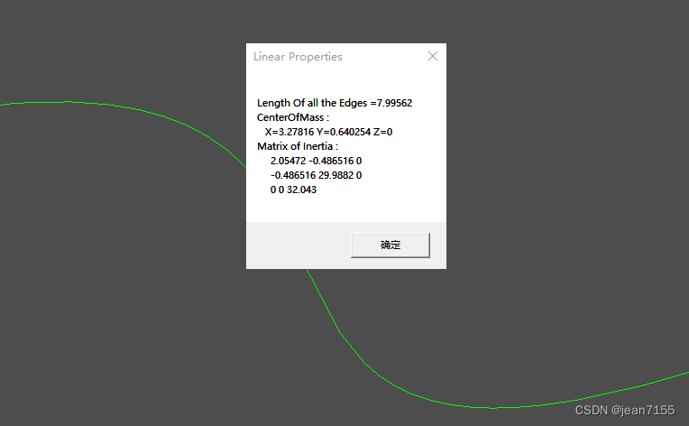
应用的类如下:
-
GeomAPI_PointsToBSpline类,描述用于构建近似一组点的 3D BSpline 曲线的函数。
-
Geom_BSplineCurve类,B 样条曲线的定义。
-
GProp_GProps类,实现一种通用机制,通过组合“基本几何实体”(例如曲线、曲面、实体、点集)的全局属性来计算 3d 空间中“复合几何系统”的全局属性。
-
BRepGProp::LinearProperties()函数,如果 LProps 的当前系统是空的,它的全局属性变得等于 S 的线性全局属性。所以,这里是获得了S的全局属性。
-
GProp_GProps类,计算的全局属性是:- 尺寸(长度、面积或体积)
- 质量,
- 质心,
- 惯性力矩(静态力矩和二次力矩),
- 绕轴的力矩,
- 绕轴线的回转半径,
- 惯性的主要性质:(另见PrincipalProps类)。主力矩,惯性主轴。主回转半径,
主要代码如下:
TColgp_Array1OfPnt Points1(1,4); Points1.SetValue(1,gp_Pnt(0,0,0)); Points1.SetValue(2,gp_Pnt(2,1,0)); Points1.SetValue(3,gp_Pnt(4,0,0)); Points1.SetValue(4,gp_Pnt(6,2,0)); GeomAPI_PointsToBSpline PTBS1(Points1); Handle(Geom_BSplineCurve) BSC1 = PTBS1.Curve(); TopoDS_Edge S = BRepBuilderAPI_MakeEdge(BSC1).Edge(); GProp_GProps System; BRepGProp::LinearProperties(S,System); gp_Pnt G = System.CentreOfMass ();//质心 Standard_Real Length = System.Mass();//边长 gp_Mat I = System.MatrixOfInertia();//惯性矩阵- 1
- 2
- 3
- 4
- 5
- 6
- 7
- 8
- 9
- 10
- 11
- 12
- 13
- 14
41、曲面的面积、质心和惯性矩阵
在void CModelingDoc::OnSurface()函数中。显示效果如下:

应用的类如下:
- GProp_GProps 类,实现一种通用机制,通过组合“基本几何实体”(例如曲线、曲面、实体、点集)的全局属性来计算 3d 空间中“复合几何系统”的全局属性。
- GeomAPI_PointsToBSpline类,描述用于构建近似一组点的 3D BSpline 曲线的函数。
- Geom_BSplineCurve类,B 样条曲线的定义。
- GeomFill_BSplineCurves类,一种用于构造 BSpline 曲面的算法,该曲面由形成其边界的连续 BSpline 曲线填充。
- Geom_BSplineSurface类,描述 BSpline 曲面。
- BRepGProp::SurfaceProperties()函数,如果 SProps 的当前系统为空,则其全局属性将等于 S 的表面全局属性。所以,这里是获得了S的全局属性。
**GProp_GProps类,计算的全局属性是:**具体见前面。
主要代码如下:
GProp_GProps System; BRepGProp::SurfaceProperties(S,System);//获得了S的全局属性。 gp_Pnt G = System.CentreOfMass ();//质心 Standard_Real Area = System.Mass();//face的面积 gp_Mat I = System.MatrixOfInertia();//惯性矩阵- 1
- 2
- 3
- 4
- 5
42、实体的体积、质心和惯性矩阵
在void CModelingDoc::OnVolume()函数中。显示效果如下:

应用的类如下:
- BRepGProp::SurfaceProperties()函数,如果当前的 VProps 系统是空的,它的全局属性就等于 S 的全局属性。所以,这里是获得了S的全局属性。
- 其他参考前面两个的内容。
主要代码如下:
GProp_GProps System; BRepGProp::VolumeProperties(S,System); gp_Pnt G = System.CentreOfMass (); Standard_Real Volume = System.Mass();//体积 gp_Mat I = System.MatrixOfInertia();- 1
- 2
- 3
- 4
- 5
43、edge修补建模(有点难懂。暂时略)
在void CModelingDoc::OnButtonFill()函数和CModelingDoc::OnStopStop()函数实现一个功能。显示效果大概是将选中的edge组成face。有点难懂。暂时略了。
应用的类如下:
- TopExp::MapShapesAndAncestors()函数,将 TS 类型的 s 的所有子形状存储在映射 M 中,每个子形状都将 TA 类型的所有唯一祖先添加到列表中。
- BRepAdaptor_Surface类,使用看起来像 3D 表面的 BRep 拓扑的面。
- GeomAdaptor_Surface类,由 Geom 包中的任何表面提供的服务与使用它的算法所需的表面之间的接口。
- BRepAdaptor_Curve2d类,BRepAdaptor 的 Curve2d 。位于 Geom 包中的曲面上的曲线提供的服务与使用该曲线的算法所需的服务之间的接口。在F上使用E的 pcurve 创建。
- Adaptor3d_CurveOnSurface类,位于 Geom 包中的曲面上的曲线提供的服务与使用该曲线的算法所需的服务之间的接口。
- GeomPlate_BuildPlateSurface类,提供了一种算法,用于构造符合给定曲线和/或点约束的板表面。该算法接受或构造一个初始表面,并寻找满足约束条件和最小化能量输入的变形。对象提供了一个框架。
- GeomPlate_MakeApprox类,允许您将 GeomPlate 曲面转换为 BSpline。
- Geom_BSplineSurface类。
- BRepTopAdaptor_FClass2d类。
44、OnFillwithtang建模(有点难懂。暂时略)
在void CModelingDoc::OnFillwithtang()函数中。
———Modeling项目。完。———
-
相关阅读:
一款基于.Net开发、开源、支持多平台云存储文件管理器
手机怎么压缩图片?通过三种压缩操作
Kotlin高仿微信-第34篇-支付-向商家付款(二维码)
Java利用AOP切面编程实现数据分页
2013 ~【VUE+ ElementUI】——【上传、下载】进度计算
Python 基于 TCP 传输协议的网络通信实现
Scrapy第十二篇:selenium4模拟器-本地代理
【Python机器学习】零基础掌握DictVectorizer特征提取
gcc和g++的爱恨纠葛
用 ZEGO Avatar 做一个虚拟人|虚拟主播直播解决方案
- 原文地址:https://blog.csdn.net/jean7155/article/details/125905850
