-
后仿真中的 《specify/endspecify block》之(5)使用specify进行时序仿真
前面我们学习了specify...endspecify 具体是什么东西。今天,我们使用specify block 中定义的延时,来进行一次仿真。看看到底是背后如何运转的呢。
一 基本例子
一个用 specify 指定延迟的与门逻辑描述如下:
- module and_gate(
- output Z,
- input A, B);
- assign Z = A & B ;
- specify
- specparam t_rise = 1.3:1.5:1.7 ;
- specparam t_fall = 1.1:1.3:1.6 ;
- (A, B *> Z) = (t_rise, t_fall) ;
- endspecify
- endmodule
一个用 specify 指定延迟的 D 触发器描述如下:
- module d_gate(
- output Q ,
- input D, CP);
- reg Q_r ;
- always @(posedge CP)
- Q_r <= D ;
- assign Q = Q_r ;
- specify
- if (D == 1'b1)
- (posedge CP => (Q +: D)) = (1.3:1.5:1.7, 1.1:1.4:1.9) ;
- if (D == 1'b0)
- (posedge CP => (Q +: D)) = (1.2:1.4:1.6, 1.0:1.3:1.8) ;
- $setup(D, posedge CP, 1);
- endspecify
- endmodule
顶层模块描述如下,主要功能是将与逻辑的输出结果输入到 D 触发器进行缓存。
- module top(
- output and_out,
- input in1, in2, clk);
- wire res_tmp ;
- and_gate u_and(res_tmp, in1, in2);
- d_gate u_dt(and_out, res_tmp, clk);
- endmodule
testbench 描述如下,仿真时设置 "+maxdelays",使用最大延迟值。
- `timescale 1ns/1ps
- module test ;
- wire and_out ;
- reg in1, in2 ;
- reg clk ;
- initial begin
- clk = 0 ;
- forever begin
- #(10/2) clk = ~clk ;
- end
- end
- initial begin
- in1 = 0 ; in2 = 0 ;
- # 32 ;
- in1 = 1 ; in2 = 1 ;
- # 13 ;
- in1 = 1 ; in2 = 0 ;
- end
- top u_top(
- .and_out (and_out),
- .in1 (in1),
- .in2 (in2),
- .clk (clk));
- initial begin
- forever begin
- #100;
- if ($time >= 1000) $finish ;
- end
- end
- endmodule // test
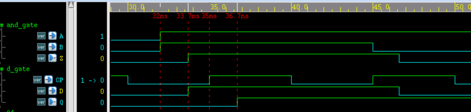
仿真时序如下所示,由图可知:
- (1) 与门输入端 A/B 到输出端 Z 的上升延迟为 33.7-32=1.7ns;
- (2) 与门输出端 Z 到触发器输入端 D 的互联延迟为 0;
- (3) 触发器 D 端到 CP 端时间差为 35-33.7=1.3ns,大于 setup check 时设置的 1ns,因此时序满足要求,不存在 violation 。
- (4) 触发器 CP 端到输出端 Q 的上升延迟为 36.7-35=1.7ns;
综上所述,仿真结果符合设计参数。
二 拓展延伸
其实,我们可以做一个延伸。修改代码如下:
- module top(
- output and_out,
- input in1, in2, clk);
- wire res_tmp;
- wire res_tmp_tmp;
- assign res_tmp_tmp = res_tmp;
- specify
- ( res_tmp => res_tmp_tmp) = (2:3:4, 3:4:5);
- endspecfiy
- and_gate u_and(res_tmp, in1, in2);
- d_gate u_dt(and_out, res_tmp_tmp, clk);
- endmodule
修改上面代码,重新进行仿真,我们会发现,Z -> D 之间,将会有 4 ns 的延时存在。

-
相关阅读:
每天5分钟快速玩转机器学习算法:支持向量机SVM的优势和缺点
【C 语言进阶(12)】动态内存管理笔试题
Python实战项目:打地鼠(源码分享)(文章较短,直接上代码)
1. 数据结构基础知识
TypeError: Argument ‘angle‘ can not be treated as a double
国际项目管理师PMP证书,值得考嘛?
【算法挨揍日记】day29——139. 单词拆分、467. 环绕字符串中唯一的子字符串
基于深度学习的任务放置在具有异质工作负载的分布式机器学习集群中的应用(论文笔记)
对卷积的一点具象化理解
11-Java中常用的API
- 原文地址:https://blog.csdn.net/qq_16423857/article/details/139888764