-
2016年新华三杯复赛实验试题
2016年新华三杯复赛实验试题
拓扑图
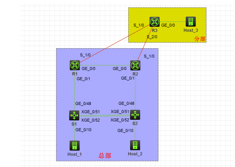
配置需求
考生根据以下配置需求在 HCL 中的设备上进行相关配置。
以太网接口配置
将 S1、S2 的以太网接口 G1/0/1 至 G1/0/16 的模式用命令 combo enable copper 激活为电口。
虚拟局域网
为了减少广播,需要规划并配置 VLAN。具体要求如下:
-
配置合理,链路上不允许不必要 VLAN 的数据流通过。
-
交换机与路由器间的互连物理端口、S1 和 S2 间的 XG1/0/51 端口直接使用三层模式互连。
-
S1 和 S2 间的 XG1/0/52 端口为 Trunk 类型。
-
为隔离网络中部分终端用户间的二层互访,在交换机 S1、S2 上使用端口隔离技术,将端口 G1/0/1 至 G1/0/4 进行二层隔离。要求隔离组编号为 1。
根据上述信息及表 2-1,在交换机上完成 VLAN 配置和端口分配。
表2-1 VLAN 分配表
设备 VLAN 编号 VLAN 名称 端口 S1、S2 VLAN10 RD G1/0/1 至 G1/0/4 VLAN20 Sales G1/0/5 至 G1/0/8 VLAN30 Supply G1/0/9 至 G1/0/12 VLAN40 Service G1/0/13 至 G1/0/16 IPv4 地址部署
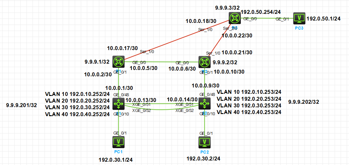
根据表 2-2,为网络设备分配 IPv4 地址。
表2-2 IPv4 地址分配表
设备 接口 IPv4 地址 S1 VLAN10 192.0.10.252/24 VLAN20 192.0.20.252/24 VLAN30 192.0.30.252/24 VLAN40 192.0.40.252/24 G1/0/48 10.0.0.1/30 XG1/0/51 10.0.0.13/30 LoopBack 0 9.9.9.201/32 S2 VLAN10 192.0.10.253/24 VLAN20 192.0.20.253/24 VLAN30 192.0.30.253/24 VLAN40 192.0.40.253/24 G1/0/48 10.0.0.9/30 XG1/0/51 10.0.0.14/30 LoopBack 0 9.9.9.202/32 R1 G0/0 10.0.0.5/30 G0/1 10.0.0.2/30 S1/0 10.0.0.17/30 LoopBack 0 9.9.9.1/32 R2 G0/0 10.0.0.6/30 G0/1 10.0.0.10/30 S1/0 10.0.0.21/30 LoopBack 0 9.9.9.2/32 R3 S1/0 10.0.0.18/30 S2/0 10.0.0.22/30 G0/0 192.0.50.254/24 LoopBack 0 9.9.9.3/32 IPv4 IGP路由部署
总部使用 OSPF 协议组网。要求网络具有安全性、稳定性。具体要求如下:
-
OSPF 进程号为 10,区域 0;
-
要求配置 OSPF 的全局 Router ID;
-
要求业务网段中不出现协议报文;
-
要求 OSPF 发布具体网段,R1 与 R2 间不建立邻居;
-
为了管理方便,需要发布 Loopback 地址;
-
优化 OSPF 相关配置,以尽量加快 OSPF 收敛;
-
不允许发布缺省路由,也不允许使用静态路由。
IPv4 BGP 路由部署
总部与分部间使用 BGP 协议。具体要求如下:
-
分部为 AS200,总部为 AS100;
-
总部内 R1、R2 需要以 LoopBack0 为源地址建立 IBGP 连接;
-
配置 BGP 的下一跳(NEXT_HOP)属性,以避免路由黑洞;
-
分部的所有路由必须通过 network 命令来发布,总部路由通过引入方式来发布;
-
通过配置 BGP 路由优先级值为 80(EBGP)、100(IBGP)、130(本地 BGP),从而避免路由环路。
-
分部向总部发布缺省路由。最终,要求全网路由互通。
路由优化部署
为了防止本路由域内始发路由被再引回到本路由域,从而造成环路,规划在从 BGP 引入路由 到 OSPF 时使用 Route-Policy 来进行过滤。具体要求如下:
-
采用给引入后路由打标签(标签值为 100)的方式来实现;
-
Route-Policy 名称为 bgp2ospf,节点(Node)编号为 10 和 20。
路由选路部署
考虑到从分部到总部有两条广域网线路,所以规划 R1-R3 间为主线路,R2-R3 间为备线路。 根据以上需求,在总部路由器上进行合理的路由协议配置。具体要求如下:
-
BGP 协议只允许使用 Route-Policy 来改变路由(192.0.0.0/16)的 MED 属性,且 MED 值必须为 100 或 200;
-
Route-Policy 名称为 MED,节点(Node)编号为 10;
-
Route-Policy 使用的 ACL 编号值为 2020,rule ID 值为 0;
-
BGP 引入路由到 OSPF 中时,需要改变引入路由的 COST 值,且其类型必须为 Type 2,引入后的路由 COST 值必须为 5 或 10;
-
Route-Policy 名称为 bgp2ospf,节点(Node)编号为 10 和 20。
PBR
考虑到分部到总部间有 2 条广域网线路,为合理利用带宽,规划从分部(192.0.50.0/24)去往 总部 VLAN10(192.0.10.0/24)的 FTP 数据流(端口号为 20 及 21)通过 R3-R1 的线路转发,从 分部(192.0.50.0/24)去往总部 VLAN40(192.0.40.0/24)的 WEB 数据流(端口号为 80 及 443) 通过 R3-R2 的线路转发。为达到上述目的,采用 PBR 来实现。参数具体要求如下:
-
policy-based-route 名称为 1,节点(Node)编号为 10 和 20;
-
分部去往总部的 FTP 数据流由 ACL3001 来定义,且其 rule ID 为 10 和 20;
-
分部去往总部的 WEB 数据流由 ACL3002 来定义,且其 rule ID 为 10 和 20。
MSTP及VRRP部署
在总部交换机 S1、S2 上配置 MSTP 防止二层环路;要求所有数据流经过 S1 转发,S1 失效时 经过 S2 转发。所配置的参数要求如下:
-
region-name 为 H3C;
-
实例值为 1;
-
S1 作为实例中的主根, S2 作为实例中的从根。
在 S1 和 S2 上配置 VRRP,实现主机的网关冗余。所配置的参数要求如表 2-3。
表2-3 S2 和 S3 的 VRRP 参数表
VLAN VRRP 备份组号(VRID) VRRP 虚拟 IP VLAN10 10 192.0.10.254 VLAN20 20 192.0.20.254 VLAN30 30 192.0.30.254 VLAN40 40 192.0.40.254 - S1 作为所有主机的实际网关,S2 作为所有主机的备份网关;其中各 VRRP 组中高优先级设置为 150,低优先级设置为 120。
QoS部署
因总部与分部间的广域网带宽有限,为了保证关键的应用,需要在设备上配置 QoS,使分部 (192.0.50.0/24)与总部 DNS 服务器(192.0.30.200)间的 DNS 数据流(UDP,端口为 53)能 够被加速转发(EF),最大带宽为链路带宽的 10%。所配置的参数要求如下:
-
ACL 编号为 3030(匹配 DNS 数据流),且其 rule ID 为 10;
-
classifier 名称为 DNS;
-
behavior 名称为 DNS;
-
QoS 策略名称为 DNS。
设备与网络管理部署
根据表 2-4,为网络设备配置主机名。
表2-4 网络设备名称表
拓扑图中设备名称 配置主机名(Sysname名) 说明 S1 S1 总部核心交换机 1 S2 S2 总部核心交换机 2 R1 R1 总部路由器 1 R2 R2 总部路由器 2 R3 R3 分部路由器 设备配置
基础 IP 配置
//R 1 Sys Sysname R 1 Int ge 0/0 Ip add 10.0.0.5 30 Undo shutdown Quit Int ge 0/1 Ip add 10.0.0.2 30 Undo shutdown Quit Int s 1/0 Ip add 10.0.0.17 30 Undo shutdown Quit Int lo 0 Ip add 9.9.9.1 32 Quit- 1
- 2
- 3
- 4
- 5
- 6
- 7
- 8
- 9
- 10
- 11
- 12
- 13
- 14
- 15
- 16
- 17
- 18
//R 2 Sys Sysname R 2 Int ge 0/0 Ip add 10.0.0.6 30 Undo shutdown Quit Int ge 0/1 Ip add 10.0.0.10 30 Undo shutdown Quit Int s 1/0 Ip add 10.0.0.21 30 Undo shutdown Quit Int lo 0 Ip add 9.9.9.2 32 Quit- 1
- 2
- 3
- 4
- 5
- 6
- 7
- 8
- 9
- 10
- 11
- 12
- 13
- 14
- 15
- 16
- 17
- 18
//R 3 Sys Sysname R 3 Int ge 0/0 Ip add 192.0.50.254 24 Undo shutdown Quit Int s 1/0 Ip add 10.0.0.18 30 Undo shutdown Quit Int s 2/0 Ip add 10.0.0.22 30 Undo shutdown Quit Int lo 0 Ip add 9.9.9.3 32 Quit- 1
- 2
- 3
- 4
- 5
- 6
- 7
- 8
- 9
- 10
- 11
- 12
- 13
- 14
- 15
- 16
- 17
- 18
//S 1 Sys Sysname S 1 Vlan 10 Vlan 20 Vlan 30 Vlan 40 Quit Int vlan 10 Ip add 192.0.10.252 24 Undo shutdown Quit Int vlan 20 Ip add 192.0.20.252 24 Undo shutdown Quit Int vlan 30 Ip add 192.0.30.252 24 Undo shutdown Quit Int vlan 40 Ip add 192.0.40.252 24 Undo shutdown Quit Int ge 1/0/48 Port link-mode route Y Ip add 10.0.0.1 30 Undo shutdown Quit Int ten-g 1/0/51 Port link-mode route Y Ip add 10.0.0.13 30 Undo shutdown Quit Int lo 0 Ip add 9.9.9.201 30 Undo shutdown Quit- 1
- 2
- 3
- 4
- 5
- 6
- 7
- 8
- 9
- 10
- 11
- 12
- 13
- 14
- 15
- 16
- 17
- 18
- 19
- 20
- 21
- 22
- 23
- 24
- 25
- 26
- 27
- 28
- 29
- 30
- 31
- 32
- 33
- 34
- 35
- 36
- 37
- 38
- 39
- 40
//S 2 Sys Sysname S 2 Vlan 10 Vlan 20 Vlan 30 Vlan 40 Quit Int vlan 10 Ip add 192.0.10.253 24 Undo shutdown Quit Int vlan 20 Ip add 192.0.20.253 24 Undo shutdown Quit Int vlan 30 Ip add 192.0.30.253 24 Undo shutdown Quit Int vlan 40 Ip add 192.0.40.253 24 Undo shutdown Quit Int ge 1/0/48 Port link-mode route Y Ip add 10.0.0.9 30 Undo shutdown Quit Int ten-g 1/0/51 Port link-mode route Y Ip add 10.0.0.14 30 Undo shutdown Quit Int lo 0 Ip add 9.9.9.202 30 Undo shutdown Quit- 1
- 2
- 3
- 4
- 5
- 6
- 7
- 8
- 9
- 10
- 11
- 12
- 13
- 14
- 15
- 16
- 17
- 18
- 19
- 20
- 21
- 22
- 23
- 24
- 25
- 26
- 27
- 28
- 29
- 30
- 31
- 32
- 33
- 34
- 35
- 36
- 37
- 38
- 39
- 40
二层配置
-------VLAN+Trunk+端口隔离------
//S 1 Sys Vlan 10 Des RD Quit Vlan 20 Des Sales Quit Vlan 30 Des Supply Quit Vlan 40 Des Service Quit Int ten-g 1/0/52 Port link-type trunk Port trunk permit vlan 10 20 30 40 Quit Int range ge 1/0/1 to ge 1/0/4 Port link-type access Port access vlan 10 Quit Int range ge 1/0/5 to ge 1/0/8 Port link-type access Port access vlan 20 Quit Int range ge 1/0/9 to ge 1/0/12 Port link-type access Port access vlan 30 Quit Int range ge 1/0/13 to ge 1/0/16 Port link-type access Port access vlan 40 Quit Port-isolate group 1 Int range ge 1/0/1 to ge 1/0/4 Port-isolate enable group 1 Quit- 1
- 2
- 3
- 4
- 5
- 6
- 7
- 8
- 9
- 10
- 11
- 12
- 13
- 14
- 15
- 16
- 17
- 18
- 19
- 20
- 21
- 22
- 23
- 24
- 25
- 26
- 27
- 28
- 29
- 30
- 31
- 32
- 33
- 34
- 35
- 36
- 37
- 38
//S 2 Sys Vlan 10 Des RD Quit Vlan 20 Des Sales Quit Vlan 30 Des Supply Quit Vlan 40 Des Service Quit Int ten-g 1/0/52 Port link-type trunk Port trunk permit vlan 10 20 30 40 Quit Int range ge 1/0/1 to ge 1/0/4 Port link-type access Port access vlan 10 Quit Int range ge 1/0/5 to ge 1/0/8 Port link-type access Port access vlan 20 Quit Int range ge 1/0/9 to ge 1/0/12 Port link-type access Port access vlan 30 Quit Int range ge 1/0/13 to ge 1/0/16 Port link-type access Port access vlan 40 Quit Port-isolate group 1 Int range ge 1/0/1 to ge 1/0/4 Port-isolate enable group 1 Quit- 1
- 2
- 3
- 4
- 5
- 6
- 7
- 8
- 9
- 10
- 11
- 12
- 13
- 14
- 15
- 16
- 17
- 18
- 19
- 20
- 21
- 22
- 23
- 24
- 25
- 26
- 27
- 28
- 29
- 30
- 31
- 32
- 33
- 34
- 35
- 36
- 37
- 38
------VRRP+MSTP------
//S 1 Sys Int vlan 10 Vrrp vrid 10 virtual-ip 192.0.10.254 Vrrp vrid 10 priority 150 Quit Int vlan 20 Vrrp vrid 20 virtual-ip 192.0.20.254 Vrrp vrid 20 priority 150 Quit Int vlan 30 Vrrp vrid 30 virtual-ip 192.0.30.254 Vrrp vrid 30 priority 150 Quit Int vlan 40 Vrrp vrid 40 virtual-ip 192.0.40.254 Vrrp vrid 40 priority 150 Quit Stp mode mstp Stp region-configuration Region-name h 3 c Instance 1 vlan 10 20 30 40 Active region-configuration Quit Stp instance 1 root primary- 1
- 2
- 3
- 4
- 5
- 6
- 7
- 8
- 9
- 10
- 11
- 12
- 13
- 14
- 15
- 16
- 17
- 18
- 19
- 20
- 21
- 22
- 23
- 24
- 25
//S 2 Sys Int vlan 10 Vrrp vrid 10 virtual-ip 192.0.10.254 Vrrp vrid 10 priority 120 Quit Int vlan 20 Vrrp vrid 20 virtual-ip 192.0.20.254 Vrrp vrid 20 priority 120 Quit Int vlan 30 Vrrp vrid 30 virtual-ip 192.0.30.254 Vrrp vrid 30 priority 120 Quit Int vlan 40 Vrrp vrid 40 virtual-ip 192.0.40.254 Vrrp vrid 40 priority 120 Quit Stp mode mstp Stp region-configuration Region-name h 3 c Instance 1 vlan 10 20 30 40 Active region-configuration Quit Stp instance 1 root secondary- 1
- 2
- 3
- 4
- 5
- 6
- 7
- 8
- 9
- 10
- 11
- 12
- 13
- 14
- 15
- 16
- 17
- 18
- 19
- 20
- 21
- 22
- 23
- 24
- 25
总部使用 OSPF
//R 1 Sys Ospf 10 router-id 9.9.9.1 Area 0 Network 9.9.9.1 0.0.0.0 Network 10.0.0.0 0.0.0.3 Quit Quit Int ge 0/1 Ospf network-type p 2 p Quit- 1
- 2
- 3
- 4
- 5
- 6
- 7
- 8
- 9
- 10
- 11
//R 2 Sys Ospf 10 router-id 9.9.9.2 Area 0 Network 9.9.9.2 0.0.0.0 Network 10.0.0.8 0.0.0.3 Quit Quit Int ge 0/1 Ospf network-type p 2 p Quit- 1
- 2
- 3
- 4
- 5
- 6
- 7
- 8
- 9
- 10
- 11
//S 1 Sys Ospf 10 router-id 9.9.9.201 Silent-int vlan 10 Silent-int vlan 20 Silent-int vlan 30 Silent-int vlan 40 Area 0 Network 9.9.9.201 0.0.0.0 Network 10.0.0.0 0.0.0.3 Network 10.0.0.12 0.0.0.3 Network 192.0.10.0 0.0.0.255 Network 192.0.20.0 0.0.0.255 Network 192.0.30.0 0.0.0.255 Network 192.0.40.0 0.0.0.255 Quit Quit Int ge 1/0/48 Ospf network-type p 2 p Quit Int ten-g 1/0/51 Ospf network-type p 2 p Quit- 1
- 2
- 3
- 4
- 5
- 6
- 7
- 8
- 9
- 10
- 11
- 12
- 13
- 14
- 15
- 16
- 17
- 18
- 19
- 20
- 21
- 22
- 23
//S 2 Sys Ospf 10 router-id 9.9.9.202 Silent-int vlan 10 Silent-int vlan 20 Silent-int vlan 30 Silent-int vlan 40 Area 0 Network 9.9.9.202 0.0.0.0 Network 10.0.0.8 0.0.0.3 Network 10.0.0.12 0.0.0.3 Network 192.0.10.0 0.0.0.255 Network 192.0.20.0 0.0.0.255 Network 192.0.30.0 0.0.0.255 Network 192.0.40.0 0.0.0.255 Quit Quit Int ge 1/0/48 Ospf network-type p 2 p Quit Int ten-g 1/0/51 Ospf network-type p 2 p Quit- 1
- 2
- 3
- 4
- 5
- 6
- 7
- 8
- 9
- 10
- 11
- 12
- 13
- 14
- 15
- 16
- 17
- 18
- 19
- 20
- 21
- 22
- 23
BGP 部分
//R 1 Sys Bgp 100 Peer 10.0.0.18 as 200 Peer 9.9.9.2 as 100 Peer 9.9.9.2 connect-int lo 0 Address ipv 4 Peer 10.0.0.18 enable Peer 9.9.9.2 enable Peer 9.9.9.2 next-hop-local Import ospf 10 Quit Quit- 1
- 2
- 3
- 4
- 5
- 6
- 7
- 8
- 9
- 10
- 11
- 12
- 13
//R 2 Sys Bgp 100 Peer 10.0.0.22 as 200 Peer 9.9.9.1 as 100 Peer 9.9.9.1 connect-int lo 0 Address ipv 4 Peer 10.0.0.22 enable Peer 9.9.9.1 enable Peer 9.9.9.1 next-hop-local Import ospf 10 Quit Quit- 1
- 2
- 3
- 4
- 5
- 6
- 7
- 8
- 9
- 10
- 11
- 12
- 13
//R 3 Bgp 200 Peer 10.0.0.17 as 100 Peer 10.0.0.21 as 200 Address ipv 4 Peer 10.0.0.17 enable Peer 10.0.0.21 enable Network 192.0.50.0 255.255.255.0 Quit Quit- 1
- 2
- 3
- 4
- 5
- 6
- 7
- 8
- 9
- 10
------配置 BGP 路由优先级------
通过配置 BGP 路由优先级值为 80(EBGP)、100(IBGP)、130(本地 BGP),从而
避免路由环路。//R 1 Sys Route-policy prefer_local permit node 10 If-match as-path 200 Apply local-preference 80 Quit Route-policy prefer_local permit node 20 If-match as-path 100 Apply local-preference 100 Quit Bgp 100 Address ipv 4 Default local-preference 130 Peer 10.0.0.18 route-policy prefer_local im Peer 9.9.9.2 route-policy prefer_local im Quit Quit- 1
- 2
- 3
- 4
- 5
- 6
- 7
- 8
- 9
- 10
- 11
- 12
- 13
- 14
- 15
- 16
- 17
//R 2 Route-policy prefer_local permit node 10 If-match as-path 200 Apply local-preference 80 Quit Route-policy prefer_local permit node 20 If-match as-path 100 Apply local-preference 100 Quit Bgp 100 Address ipv 4 Default local-preference 130 Peer 10.0.0.22 route-policy prefer_local im Peer 9.9.9.1 route-policy prefer_local im Quit Quit- 1
- 2
- 3
- 4
- 5
- 6
- 7
- 8
- 9
- 10
- 11
- 12
- 13
- 14
- 15
- 16
//R 3 Sys Route-policy prefer_local permit node 10 If-match as-path 100 Apply local-preference 80 Quit Bgp 200 Address ipv 4 Default local-preference 130 Peer 10.0.0.17 route-policy prefer_local im Peer 10.0.0.21 route-policy prefer_local im Quit Quit- 1
- 2
- 3
- 4
- 5
- 6
- 7
- 8
- 9
- 10
- 11
- 12
- 13
------BGP 下发缺省路由------
//R 3 Sys Ip route-static 0.0.0.0 0.0.0.0 Bgp 200 Address ipv 4 Network 0.0.0.0 0.0.0.0 Quit Quit- 1
- 2
- 3
- 4
- 5
- 6
- 7
- 8
路由优化和选路部署
//R 1 Sys Acl basic 2000 Rule 5 permit source 192.0.50.0 0.0.0.255 Quit Route-policy bgp2ospf permit node 10 If-match ip address acl 2000 Apply tag 100 Quit Route-policy bgp2ospf deny node 20 Quit Ospf 10 Import-route bgp 100 route-policy bgp 2 ospf type 2 cost 5 Quit Acl basic 2020 Rule 0 permit source 192.0.0.0 0.0.255.255 Quit Route-policy MED permit node 10 If-match ip address acl 2020 Apply cost 100 Quit Bgp 100 Address ipv 4 Peer 10.0.0.18 route-policy MED ex Quit Quit- 1
- 2
- 3
- 4
- 5
- 6
- 7
- 8
- 9
- 10
- 11
- 12
- 13
- 14
- 15
- 16
- 17
- 18
- 19
- 20
- 21
- 22
- 23
- 24
- 25
- 26
//R 2 Sys Acl basic 2000 Rule 5 permit source 192.0.50.0 0.0.0.255 Quit Route-policy bgp2ospf permit node 10 If-match ip address acl 2000 Apply tag 100 Quit Route-policy bgp2ospf deny node 20 Quit Ospf 10 Import-route bgp 100 route-policy bgp 2 ospf type 2 cost 10 Quit Acl basic 2020 Rule 0 permit source 192.0.0.0 0.0.255.255 Quit Route-policy MED permit node 10 If-match ip address acl 2020 Apply cost 200 Quit Bgp 100 Address ipv 4 Peer 10.0.0.22 route-policy MED ex Quit Quit- 1
- 2
- 3
- 4
- 5
- 6
- 7
- 8
- 9
- 10
- 11
- 12
- 13
- 14
- 15
- 16
- 17
- 18
- 19
- 20
- 21
- 22
- 23
- 24
- 25
- 26
//R 3 Sys Bgp 200 Compare-differemt-as-med Quit Quit- 1
- 2
- 3
- 4
- 5
- 6
PBR 部分
//R 3 Sys Acl advanced 3001 Rule 10 permit tcp source 192.0.50.0 0.0.0.255 source-port eq 21 destination 192.0.10.0 0.0.0.255 destination-port eq 21 Rule 20 permit tcp source 192.0.50.0 0.0.0.255 source-port eq 20 destination 192.0.10.0 0.0.0.255 destination-port eq 20 Quit Acl advanced 3002 Rule 10 permit tcp source 192.0.50.0 0.0.0.255 source-port eq 80 destination 192.0.40.0 0.0.0.255 destination-port eq 80 Rule 10 permit tcp source 192.0.50.0 0.0.0.255 source-port eq 443 destination 192.0.40.0 0.0.0.255 destination-port eq 443 Quit Route-policy 1 permit node 10 If-match ip address acl 3001 Apply ip-address next-hop 10.0.0.17 Quit Route-policy 1 permit node 20 If-match ip address acl 3002 Apply ip-address next-hop 10.0.0.21 Quit- 1
- 2
- 3
- 4
- 5
- 6
- 7
- 8
- 9
- 10
- 11
- 12
- 13
- 14
- 15
- 16
- 17
- 18
Qos 部署
//R 3 Sys Acl advanced 3030 Rule 10 permit udp source 192.0.50.0 0.0.0.255 source-port eq 53 destination 192.0.30.200 0.0.0.0 destination-port eq 53 Quit Traffic classifier DNS operator or If-match acl 3030 Quit Traffic behavior DNS Car cir percent 10 Remark dscp ef Quit Qos policy DNS Classifier DNS behavior DNS Quit Int range se 1/0 se 2/0 Qos apply policy DNS outbound Quit- 1
- 2
- 3
- 4
- 5
- 6
- 7
- 8
- 9
- 10
- 11
- 12
- 13
- 14
- 15
- 16
- 17
- 18
华三设备开启 tracert
//device Sys Ip ttl-expires enable Ip unreachables enable- 1
- 2
- 3
- 4
-
-
相关阅读:
2022全国水下机器人大赛国际线上赛来啦!“水下感知赛、通信赛”等你来战!
家电生产线数控机床上下料长臂机器人组设计
某大厂软件测试岗一面笔试题+二面问答题面试经验分享
社交媒体变革者:剖析Facebook对在线互动的贡献
前端食堂技术周刊第 49 期:Deno即将迎来重大变革、Blitz 2.0 Beta、Chrome删除HTTP/2服务端推送
Certificate verification failed: The certificate is NOT trusted
贝叶斯建模:从先验合理性到后验分布
秒验丨Android端SDK API使用说明
如果老师这么讲面向对象,当年我就不会挂科了吧
直播互动流程
- 原文地址:https://blog.csdn.net/qq_64050217/article/details/137963966