-
【FPGA】FPGA实现UART串口通信回环
一、UART协议基础
关于UART协议的基础理论部分已经在上一篇文章中讲述,不再重复介绍。
UART通信协议
本文主要介绍如何使用Verlilog编程,通过FPGA实现UART串口通信回环工程。在本工程中所使用的系统时钟为50MHz,如果选择115200的波特率进行数据传输,那么传输1bit所用的时钟周期数就是50_000_000 / 115200。二、系统模块划分
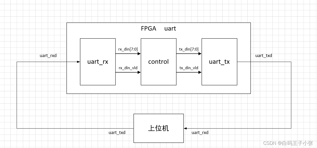
uart模块: uart串口通信顶层设计模块,包含uart_tx、uart_rx、control模块。
uart_rx模块: UART串口数据接收模块,将上位机发送的串行数据接收后转换成并行数据发送给control模块。
control模块: UART控制模块,将接收到的并行数据存储到FIFO中,当读FIFO条件满足时输出。
uart_tx模块: UART串口数据发送模块,将从control读出的并行数据转换成串行数据发送给上位机。三、代码实现
1、uart顶层设计模块
// ************************************************************** // Author: Zhang JunYi // Create Date: 2022.11.04 // Design Name: uart // Module Name: uart // Target Device: Cyclone IV E (EP4CE6F17C8) // Tool versions: Quartus Prime 18.1 // Description: UART串口通信顶层设计模块 // ************************************************************** module uart ( input clk , input rst_n , input uart_rxd , output uart_txd ); // 信号定义 wire [7:0] rx_dout ; wire rx_dout_vld ; wire [7:0] ctrl_dout ; wire ctrl_dout_vld ; wire ready ; // 模块例化 uart_rx u_uart_rx ( /*input */.clk (clk ), /*input */.rst_n (rst_n ), /*input */.uart_rx (uart_rxd ), // 接收到的串口数据 /*output [7:0] */.rx_dout (rx_dout ), // 串行数据转换成并行数据后输出给control模块 /*output */.rx_dout_vld (rx_dout_vld ) ); control u_control ( /*input */.clk (clk ), /*input */.rst_n (rst_n ), /*// uart_rx*/ /*input [7:0] */.rx_din (rx_dout ), /*input */.rx_din_vld (rx_dout_vld ), /*// uart_tx*/ /*input */.ready (ready ), /*output [7:0] */.ctrl_dout (ctrl_dout ), /*output */.ctrl_dout_vld (ctrl_dout_vld ) ); uart_tx u_uart_tx ( /*input */.clk (clk ), /*input */.rst_n (rst_n ), /*// control*/ /*input [7:0] */.tx_din (ctrl_dout ), /*input */.tx_din_vld (ctrl_dout_vld ), /*output */.ready (ready ), // 给control模块的握手信号,表示可以接收数据进行发送 /*// 上位机*/ /*output */.uart_tx (uart_txd ) ); endmodule- 1
- 2
- 3
- 4
- 5
- 6
- 7
- 8
- 9
- 10
- 11
- 12
- 13
- 14
- 15
- 16
- 17
- 18
- 19
- 20
- 21
- 22
- 23
- 24
- 25
- 26
- 27
- 28
- 29
- 30
- 31
- 32
- 33
- 34
- 35
- 36
- 37
- 38
- 39
- 40
- 41
- 42
- 43
- 44
- 45
- 46
- 47
- 48
- 49
- 50
- 51
- 52
- 53
- 54
- 55
- 56
- 57
- 58
- 59
- 60
2、uart_rx串口数据接收模块
// ************************************************************** // Author: Zhang JunYi // Create Date: 2022.11.04 // Design Name: uart // Module Name: uart_rx // Target Device: Cyclone IV E (EP4CE6F17C8) // Tool versions: Quartus Prime 18.1 // Description: UART串口通信数据接收模块 // ************************************************************** `include "param.v" module uart_rx ( input clk , input rst_n , input uart_rx , // 接收到的串口数据 output [7:0] rx_dout , // 串行数据转换成并行数据后输出给control模块 output rx_dout_vld ); // 参数定义 // 信号定义 reg [19:0] cnt_baud ; // 波特率计数器 wire add_cnt_baud ; wire end_cnt_baud ; reg [3:0] cnt_bit ; // bit计数器 wire add_cnt_bit ; wire end_cnt_bit ; reg rx_flag ; // 开始接收数据标志 reg [1:0] uart_rx_r ; // uart_rx同步打拍 wire rx_nedge ; // uart_rx下降沿 reg [9:0] dout_data ; // cnt_baud always @(posedge clk or negedge rst_n)begin if(!rst_n)begin cnt_baud <= 0 ; end else if(add_cnt_baud)begin if(end_cnt_baud)begin cnt_baud <= 0 ; end else begin cnt_baud <= cnt_baud + 1 ; end end end assign add_cnt_baud = rx_flag ; assign end_cnt_baud = add_cnt_baud && (cnt_baud == `BAUD - 1) ; // cnt_bit always @(posedge clk or negedge rst_n)begin if(!rst_n)begin cnt_bit <= 0 ; end else if(add_cnt_bit)begin if(end_cnt_bit)begin cnt_bit <= 0 ; end else begin cnt_bit <= cnt_bit + 1 ; end end end assign add_cnt_bit = end_cnt_baud ; assign end_cnt_bit = add_cnt_bit && (cnt_bit == 9 || dout_data[0] == 1'b1) ; // uart_rx_r always @(posedge clk or negedge rst_n)begin if(!rst_n)begin uart_rx_r <= 0 ; end else begin uart_rx_r <= {uart_rx_r[0],uart_rx} ; end end // uart_rx下降沿检测 assign rx_nedge = ~uart_rx_r[0] & uart_rx_r[1] ; // rx_flag always @(posedge clk or negedge rst_n)begin if(!rst_n)begin rx_flag <= 1'b0 ; end else if(rx_nedge)begin rx_flag <= 1'b1 ; end else if(end_cnt_bit)begin rx_flag <= 1'b0 ; end end // dout_data always @(posedge clk or negedge rst_n)begin if(!rst_n)begin dout_data <= 0 ; end else if(rx_flag & cnt_baud == 0)begin dout_data[cnt_bit] <= uart_rx_r[0] ; end end // 输出 assign rx_dout = dout_data[8:1] ; assign rx_dout_vld = end_cnt_bit && dout_data[0] == 1'b0 ; endmodule- 1
- 2
- 3
- 4
- 5
- 6
- 7
- 8
- 9
- 10
- 11
- 12
- 13
- 14
- 15
- 16
- 17
- 18
- 19
- 20
- 21
- 22
- 23
- 24
- 25
- 26
- 27
- 28
- 29
- 30
- 31
- 32
- 33
- 34
- 35
- 36
- 37
- 38
- 39
- 40
- 41
- 42
- 43
- 44
- 45
- 46
- 47
- 48
- 49
- 50
- 51
- 52
- 53
- 54
- 55
- 56
- 57
- 58
- 59
- 60
- 61
- 62
- 63
- 64
- 65
- 66
- 67
- 68
- 69
- 70
- 71
- 72
- 73
- 74
- 75
- 76
- 77
- 78
- 79
- 80
- 81
- 82
- 83
- 84
- 85
- 86
- 87
- 88
- 89
- 90
- 91
- 92
- 93
- 94
- 95
- 96
- 97
- 98
- 99
- 100
- 101
- 102
- 103
- 104
- 105
- 106
- 107
- 108
- 109
- 110
- 111
- 112
3、control控制模块
// ************************************************************** // Author: Zhang JunYi // Create Date: 2022.11.04 // Design Name: uart // Module Name: control // Target Device: Cyclone IV E (EP4CE6F17C8) // Tool versions: Quartus Prime 18.1 // Description: UART串口通信控制模块 // ************************************************************** `include "param.v" module control ( input clk , input rst_n , // uart_rx input [7:0] rx_din , input rx_din_vld , // uart_tx input ready , output [7:0] ctrl_dout , output ctrl_dout_vld ); // 参数定义 // 信号定义 wire rdreq ; wire wrreq ; wire [7:0] fifo_q ; wire rdempty ; wire [2:0] rdusedw ; wire wrfull ; wire [2:0] wrusedw ; reg rd_flag ; // fifo可读标志 // rd_flag always @(posedge clk or negedge rst_n)begin if(!rst_n)begin rd_flag <= 1'b0 ; end else if(rdusedw > 4)begin rd_flag <= 1'b1 ; end else if(rdempty)begin rd_flag <= 1'b0 ; end end // fifo例化 fifo fifo_inst ( .aclr ( ~rst_n ), .data ( rx_din ), .rdclk ( clk ), .rdreq ( rdreq ), .wrclk ( clk ), .wrreq ( wrreq ), .q ( fifo_q ), .rdempty ( rdempty ), .rdusedw ( rdusedw ), .wrfull ( wrfull ), .wrusedw ( wrusedw ) ); assign wrreq = ~wrfull && rx_din_vld ; assign rdreq = rd_flag && ready ; // 输出 assign ctrl_dout = fifo_q ; assign ctrl_dout_vld = rdreq ; endmodule- 1
- 2
- 3
- 4
- 5
- 6
- 7
- 8
- 9
- 10
- 11
- 12
- 13
- 14
- 15
- 16
- 17
- 18
- 19
- 20
- 21
- 22
- 23
- 24
- 25
- 26
- 27
- 28
- 29
- 30
- 31
- 32
- 33
- 34
- 35
- 36
- 37
- 38
- 39
- 40
- 41
- 42
- 43
- 44
- 45
- 46
- 47
- 48
- 49
- 50
- 51
- 52
- 53
- 54
- 55
- 56
- 57
- 58
- 59
- 60
- 61
- 62
- 63
- 64
- 65
- 66
- 67
- 68
- 69
- 70
- 71
- 72
4、uart_tx串口数据发送模块
// ************************************************************** // Author: Zhang JunYi // Create Date: 2022.11.04 // Design Name: uart // Module Name: uart_tx // Target Device: Cyclone IV E (EP4CE6F17C8) // Tool versions: Quartus Prime 18.1 // Description: UART串口通信数据发送模块模块 // ************************************************************** `include "param.v" module uart_tx ( input clk , input rst_n , // control input [7:0] tx_din , input tx_din_vld , output ready , // 给control模块的握手信号,表示可以接收数据进行发送 // 上位机 output uart_tx ); // 参数定义 // 信号定义 reg [19:0] cnt_baud ; // 波特率计数器 wire add_cnt_baud ; wire end_cnt_baud ; reg [3:0] cnt_bit ; // bit计数器 wire add_cnt_bit ; wire end_cnt_bit ; reg tx_flag ; // 数据传输标志 reg [9:0] tx_data ; // 寄存将要发送的数据 reg dout ; // 并行数据转串行数据发送 reg vld ; // cnt_baud always @(posedge clk or negedge rst_n)begin if(!rst_n)begin cnt_baud <= 0 ; end else if(add_cnt_baud)begin if(end_cnt_baud)begin cnt_baud <= 0 ; end else begin cnt_baud <= cnt_baud + 1 ; end end end assign add_cnt_baud = tx_flag ; assign end_cnt_baud = add_cnt_baud && (cnt_baud == `BAUD - 1) ; // cnt_bit always @(posedge clk or negedge rst_n)begin if(!rst_n)begin cnt_bit <= 0 ; end else if(add_cnt_bit)begin if(end_cnt_bit)begin cnt_bit <= 0 ; end else begin cnt_bit <= cnt_bit + 1 ; end end end assign add_cnt_bit = end_cnt_baud ; assign end_cnt_bit = add_cnt_bit && (cnt_bit == 9) ; // tx_flag always @(posedge clk or negedge rst_n)begin if(!rst_n)begin tx_flag <= 1'b0 ; end else if(tx_din_vld)begin tx_flag <= 1'b1 ; end else if(end_cnt_bit)begin tx_flag <= 1'b0 ; end end // vld always @(posedge clk or negedge rst_n)begin if(!rst_n)begin vld <= 1'b0 ; end else begin vld <= tx_din_vld ; end end // tx_data always @(posedge clk or negedge rst_n)begin if(!rst_n)begin tx_data <= 0 ; end else if(vld)begin tx_data <= {1'b1,tx_din,1'b0} ; // 停止位 + 数据 + 起始位 低位在前发送 end end // dout always @(posedge clk or negedge rst_n)begin if(!rst_n)begin dout <= 1'b1 ; end else if(tx_flag)begin dout <= tx_data[cnt_bit] ; end end // 输出 assign uart_tx = dout ; assign ready = ~tx_flag ; endmodule- 1
- 2
- 3
- 4
- 5
- 6
- 7
- 8
- 9
- 10
- 11
- 12
- 13
- 14
- 15
- 16
- 17
- 18
- 19
- 20
- 21
- 22
- 23
- 24
- 25
- 26
- 27
- 28
- 29
- 30
- 31
- 32
- 33
- 34
- 35
- 36
- 37
- 38
- 39
- 40
- 41
- 42
- 43
- 44
- 45
- 46
- 47
- 48
- 49
- 50
- 51
- 52
- 53
- 54
- 55
- 56
- 57
- 58
- 59
- 60
- 61
- 62
- 63
- 64
- 65
- 66
- 67
- 68
- 69
- 70
- 71
- 72
- 73
- 74
- 75
- 76
- 77
- 78
- 79
- 80
- 81
- 82
- 83
- 84
- 85
- 86
- 87
- 88
- 89
- 90
- 91
- 92
- 93
- 94
- 95
- 96
- 97
- 98
- 99
- 100
- 101
- 102
- 103
- 104
- 105
- 106
- 107
- 108
- 109
- 110
- 111
- 112
- 113
- 114
- 115
- 116
- 117
- 118
- 119
- 120
- 121
- 122
- 123
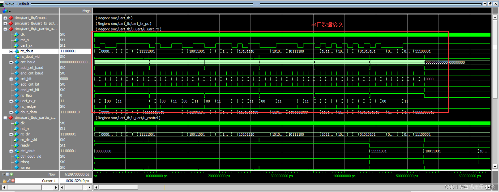
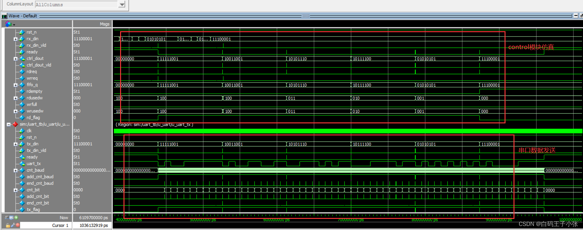
四、仿真
仿真代码如下:
`timescale 1ns/1ps module uart_tb (); reg tb_clk ; reg tb_rst_n ; reg [7:0] data ; reg data_vld ; wire ready ; wire tx_data ; wire uart_txd ; wire [7:0] rx_dout ; wire rx_dout_vld ; // 模块例化 uart_tx uart_tx_pc ( // 模拟上位机发送数据 /*input */.clk (tb_clk ), /*input */.rst_n (tb_rst_n ), /*// control*/ /*input [7:0] */.tx_din (data ), /*input */.tx_din_vld (data_vld ), /*output */.ready (ready ), // 给control模块的握手信号,表示可以接收数据进行发送 /*// 上位机*/ /*output */.uart_tx (tx_data ) ); uart u_uart ( /*input */.clk (tb_clk ), /*input */.rst_n (tb_rst_n ), /*input */.uart_rxd (tx_data ), /*output */.uart_txd (uart_txd ) ); // 参数定义 parameter CYCLE = 20 ; always #(CYCLE / 2) tb_clk = ~tb_clk ; // 50M时钟 initial begin tb_clk = 1'b1; tb_rst_n = 1'b1; data = 0; data_vld = 1'b0; # (CYCLE * 2); tb_rst_n = 1'b0; # (CYCLE * 2); # 2; tb_rst_n = 1'b1; # (CYCLE * 10); Send(8'hf9); Send(8'h99); Send(8'hAE); Send(8'hBC); Send(8'h55); Send(8'hE1); # (CYCLE * 100); $stop; end task Send; input [7:0] send_data ; begin data = send_data ; data_vld = 1'b1 ; # CYCLE ; data_vld = 1'b0 ; // @(posedge ready) # (CYCLE*440*10) ; end endtask endmodule- 1
- 2
- 3
- 4
- 5
- 6
- 7
- 8
- 9
- 10
- 11
- 12
- 13
- 14
- 15
- 16
- 17
- 18
- 19
- 20
- 21
- 22
- 23
- 24
- 25
- 26
- 27
- 28
- 29
- 30
- 31
- 32
- 33
- 34
- 35
- 36
- 37
- 38
- 39
- 40
- 41
- 42
- 43
- 44
- 45
- 46
- 47
- 48
- 49
- 50
- 51
- 52
- 53
- 54
- 55
- 56
- 57
- 58
- 59
- 60
- 61
- 62
- 63
- 64
- 65
- 66
- 67
- 68
- 69
- 70
- 71
- 72
- 73
- 74
- 75
- 76
- 77
- 78
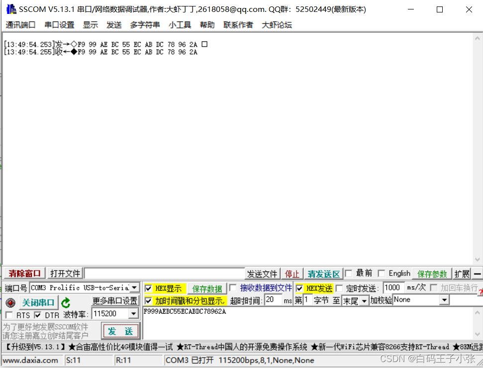
五、上板验证
这里通过串口调试助手来与FPGA进行串口通信测试,可以看见通过串口收发数据正确。
六、踩坑事项
在调试串口的时候发现设备管理器中串口无法识别,显示PL2303HXA自2012已停产,请联系供应商,如下图:
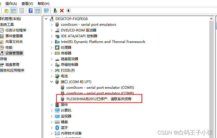
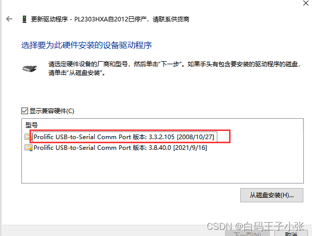
这时需要下载一个旧版本的驱动,下载链接如下:
链接:https://pan.baidu.com/s/1FTtfgc2k2fw-9Ck1_tRbRQ
提取码:7kf2下载完成后解压安装,点击更新驱动程序→浏览电脑选择旧版本双击安装即可:
-
相关阅读:
package.json文件的一些知识点,实践总结
【JAVA】JSP
java毕业生设计宠物店管理计算机源码+系统+mysql+调试部署+lw
反虚拟机、反沙箱技术整理汇总
Amazon云计算AWS(三)
前端录入音频并上传
【初阶与进阶C++详解】第十一篇:stack和queue
Javascript知识【案例:复选框操作】
数据大帝国:大数据与人工智能的巅峰融合
离线强化学习(Offline RL)系列7: (状态处理)Koopman-Q学习:通过动力学对称性的状态空间数据增强方法
- 原文地址:https://blog.csdn.net/weixin_45137708/article/details/127703003
