-
lego-loam 跑 kitti00包(kitti2bag+lego-loam+evo)详细版
kitti数据包的使用
kitti开源数据集的官网:http://www.cvlibs.net/datasets/kitti/eval_odometry.php

我使用的就是官网封面的包,下载下来后,先查看每个包里面都有什么,因为笔者本次只跑了00以作示例,将下载后的包凑凑拼拼,组成一个文件夹,里面包含这些文件(本次示例不使用IMU):dataset_folder |____results |____00.txt |____sequences |_____00 |___image_0 |___image_1 |___velodyne |___times.txt |___calib.txt- 1
- 2
- 3
- 4
- 5
- 6
- 7
- 8
- 9
- 10
打开文件可以查看到kitti的bag保存形式为.bin形式,这对于ros环境不是特别友好,因此我们就得将kitti的.bin转换为.bag,就可以直接使用rosbag的命令直接跑了,比较方便。因此需要写一个代码来进行转换。当然此类代码就比较多了,在这里笔者介绍笔者接触到的两个代码:
lidar2rosbag_KITTI
开源代码:https://github.com/AbnerCSZ/lidar2rosbag_KITTI
阅读README,进行下载编译,按照要求将所需要的文件放置在对应的文件夹即可,然后运行指定的命令:└── dataset └── sequences └── 04 ├── calib.txt ├── image_0 [271 entries exceeds filelimit, not opening dir] ├── image_1 [271 entries exceeds filelimit, not opening dir] ├── times.txt └── velodyne [271 entries exceeds filelimit, not opening dir]- 1
- 2
- 3
- 4
- 5
- 6
- 7
- 8
运行格式: rosrun lidar2rosbag lidar2rosbag KITTI_input_dir output_name 示例: rosrun lidar2rosbag lidar2rosbag /data/KITTI/dataset/sequences/04/ 04 或者 rosrun lidar2rosbag lidar2rosbag /data/KITTI/dataset/sequences/01/ bag01- 1
- 2
- 3
- 4
- 5
- 6
生成的bag信息为:

这里突出介绍一下这个代码的优点和缺点:
优点:这个代码将点云数据的时间戳直接跟kitti数据集的时间戳对应,即从0s开始,一直到470s
缺点:这个代码生成的bag里面的话题只有点云:/velodyne_points,没有其他的话题了。另外:有些人觉得生成bag文件会占用一些空间,因此就不生成bag了,直接在读取.bin文件时转换成PointCloud2进行发布话题,具体的可以参考关于KITTI数据中点云bin文件转成rosbag包的方法
kitti-lego-loam
代码:https://github.com/Mitchell-Lee-93/kitti-lego-loam
这个code里面其实是两个包,一个是将kitti数据集转换成bag,另一个就是修改了一点的lego-loam代码:1.修改雷达参数(kitti数据集的lidar是64线)2.关闭了运动补偿 3.为了评测,保存了位姿数据。
这里在转换成bag时,需要注意一下文件的存放顺序:
dataset_folder |____results |____00.txt |____sequences |_____00 |___image_0 |___image_1 |___velodyne |___times.txt |___calib.txt- 1
- 2
- 3
- 4
- 5
- 6
- 7
- 8
- 9
- 10
在运行kittibag时,记得修改kittibag.launch里的内容:

然后运行roslaunch kittibag kittibag.launch- 1
有可能会出现下面这个错误:

经过我查寻解决方案后,得到的解决方案:
第一次解决:将roscore关掉,重新再打开。
第二次解决:将times.txt文件的开始时间比0大一点点(不能为0)

生成bag的信息为:

这里可能是因为使用了ROS::Time()的原因导致这个包有626s跟470s不一样。然后介绍一下这种方式的优点和缺点:
1.优点:话题里除了lidar的点云较上一种方法,还包含了相机和真值话题,我很喜欢!
2.缺点:生成bag文件的时间戳是当时转换bag时的时间戳ROS::Time(),因此在rosbag play --clock 00.bag时,lego-loam的rviz不会显示当前正在构建的地图(时间不一致)
因此,笔者结合这两种方法,修改了第二种方法,解决了第二种方法的缺点,得到了我想要的bag。具体的修改方式为:只修改第164行代码为如下形式:if (to_bag) { bag_out.write("/image_left", ros::Time().fromSec(timestamp), image_left_msg); bag_out.write("/image_right", ros::Time().fromSec(timestamp), image_right_msg); bag_out.write("/kitti/velo/pointcloud", ros::Time().fromSec(timestamp), laser_cloud_msg); bag_out.write("/path_gt", ros::Time().fromSec(timestamp), pathGT); bag_out.write("/odometry_gt", ros::Time().fromSec(timestamp), odomGT); // bag_out.write("/image_left", ros::Time::now(), image_left_msg); // bag_out.write("/image_right", ros::Time::now(), image_right_msg); // bag_out.write("/kitti/velo/pointcloud", ros::Time::now(), laser_cloud_msg); // bag_out.write("/path_gt", ros::Time::now(), pathGT); // bag_out.write("/odometry_gt", ros::Time::now(), odomGT); }- 1
- 2
- 3
- 4
- 5
- 6
- 7
- 8
- 9
- 10
- 11
- 12
- 13
- 14
- 15
修改过后再次生成的bag信息为:

这次时间就是从0开始了,然后直接跑lego-loam就可以在rviz中看到在线建立的图像了。但是当我跑lego-loam时,几乎很大的概率会炸,就是漂的离谱的那种,乱七八糟的:

先不说回环不回环的问题,我看的别人跑的不使用回环效果都比这个好,比如这里,但是还有这里他也漂的离谱,我觉得不是加没加回环的问题,因为,我测试过,加回环也是这样。哈哈哈哈哈。啊呸,怎么笑的出来的。。。经过我一番检测问题,找到了问题所在,就是我rosbag play时,中间会卡几下,严重的中间直接给我卡没了40s,40s的数据没了,再TM牛逼的代码估计也不好使吧。于是我心里想着,是不是电脑不行了(得找老板要台新电脑了)。。。 但是,这电脑也不能下一秒就到吧,但是我这科研绝不能因为一台电脑耽误,因此只能另寻方法(实则是比较卑微,不敢要电脑)。

于是,参考了大文件rosbag播放太慢问题解决,虽然题主说的不是我这个问题,但是题主说的问题,我也遇到了,同时bag文件太大了不得不压缩压缩,因此使用下面这条命令将bag进行了压缩。rosbag compress --lz4 *.bag- 1

压缩后的bag信息如下图所示:确实小了很多

我使用压缩后的bag跑lego-loam,确实好了些,但是不稳定,几乎每次跑都不一样,有时候偏的多一点,有时候就挺好的,不知道大家是不是这种情况,以至于,我觉得读取数据速度的原因,因为我是将bag文件放在机械硬盘里面的,后来我将bag放在了固态里面,稳定性又提升了一个台阶。后来经过与网友@琦琦酱_ 讨论得出内存不够,他用的是虚拟机,分配内存多一点就好了很多。
lego-loam运行
上面的跑包问题解决了,就直接上实验结果了。
跑包之前时,先对lego-loam进行一个小改动,
1,首先kitti-lego-loam已经对lego-loam修改了,即生成姿态信息,代码在transformFusion.cpp里面的line223。生成结果的路径需要在run.launch里修改【已修改,自己不用修改】笔者想法:经过笔者实验这个生成的姿态不是优化后的姿态,优化后的姿态不能实时保存,而应该最后全部跑完时保存(因为最后可能有回环,会调整前面的位姿),因此这个位姿是实时的位姿,与GT对比时误差会比较大。

/added, cout results/// Eigen::Quaterniond q; q.w()=laserOdometry2.pose.pose.orientation.w; q.x()=laserOdometry2.pose.pose.orientation.x; q.y()=laserOdometry2.pose.pose.orientation.y; q.z()=laserOdometry2.pose.pose.orientation.z; Eigen::Matrix3d R = q.toRotationMatrix(); if (init_flag==true) { H_init<< R.row(0)[0],R.row(0)[1],R.row(0)[2],transformMapped[3], R.row(1)[0],R.row(1)[1],R.row(1)[2],transformMapped[4], R.row(2)[0],R.row(2)[1],R.row(2)[2],transformMapped[5], 0,0,0,1; init_flag=false; std::cout<<"surf_th : "<<surfThreshold<<endl; } H_rot<< -1,0,0,0, 0,-1,0,0, 0,0,1,0, 0,0,0,1; H<< R.row(0)[0],R.row(0)[1],R.row(0)[2],transformMapped[3], R.row(1)[0],R.row(1)[1],R.row(1)[2],transformMapped[4], R.row(2)[0],R.row(2)[1],R.row(2)[2],transformMapped[5], 0,0,0,1; H = H_rot*H_init.inverse()*H; //to get H12 = H10*H02 , 180 rot according to z axis std::ofstream foutC(RESULT_PATH, std::ios::app); foutC.setf(std::ios::scientific, std::ios::floatfield); foutC.precision(6); //foutC << R[0] << " "<- 1
- 2
- 3
- 4
- 5
- 6
- 7
- 8
- 9
- 10
- 11
- 12
- 13
- 14
- 15
- 16
- 17
- 18
- 19
- 20
- 21
- 22
- 23
- 24
- 25
- 26
- 27
- 28
- 29
- 30
- 31
- 32
- 33
- 34
- 35
- 36
- 37
- 38
- 39
- 40
- 41
- 42
- 43
- 44
- 45
- 46
- 47
- 48
- 49
- 50
- 51
- 52
- 53
- 54
- 55
- 56
- 57
- 58
- 59
- 60
- 61
- 62
- 63
- 64
- 65
2,修改:增加实时地图中路径的显示【未修改,需要自行添加】
在utility.h
#include <nav_msgs/Path.h>- 1
在transformfusion.cpp
//在line48前后增加 nav_msgs::Path laserAfterMappedPath; //在line48前后增加 ros::Publisher pubLaserAfterMappedPath; //在line79前后增加 pubLaserAfterMappedPath = nh.advertise<nav_msgs::Path>("/aft_mapped_path", 100); //在line230前后增加 geometry_msgs::PoseStamped laserAfterMappedPose; laserAfterMappedPose.header = laserOdometry2.header; laserAfterMappedPose.pose = laserOdometry2.pose.pose; laserAfterMappedPath.header.stamp = laserOdometry2.header.stamp; laserAfterMappedPath.header.frame_id = "/camera_init"; laserAfterMappedPath.poses.push_back(laserAfterMappedPose); pubLaserAfterMappedPath.publish(laserAfterMappedPath);- 1
- 2
- 3
- 4
- 5
- 6
- 7
- 8
- 9
- 10
- 11
- 12
- 13
- 14
- 15
- 16
- 17
- 18
笔者想法:这一步修改是参考了LeGO-LOAM运行kitti数据集,作者说是优化后的路径显示,其实经过我自己的实验,以及代码查看,认为这不是优化后的路径(我指的优化是回环检测),而是目前实时的路径。
实验结果如下:

lego-loam是否使用回环就在utility.h里面的line104里修改 loopClosureEnableFlag就可以。无回环:


从这两张图片可以看到,当没有回环时,代码自己的轨迹与自行添加的实时轨迹一摸一样,而当加上回环时,就不一样了。

有回环:


这三张图中最左边的是实时的路径信息,最右边的是回环优化后的路径信息。中间是两者的结合。从最左边可以看到一些细节,就是路径突然变正,没错,那就是回环检测矫正。

rviz中显示gt轨迹和实时轨迹和优化后的轨迹
因为kittibag里面把真值路径和真值里程计也转化成了话题,因此在lego-loam运行时不显示它,就挺对不起这两个话题的。。。哈哈哈。
因此,在运行时就将gt、实时、优化三种轨迹全都画出来,进行实时对比。
首先,需要对代码进行更改,更改1: 因为kittibag里面将真值输出时,frame_id为“/camera_init”,如果直接显示,会因为run.launch里面对camera_init到map进行了旋转,因此真值并不能与另外两个轨迹显示在一个平面,绕了某两个轴旋转了90°,因此,为了解决这个问题,就将bag里面gt的frame_id变成其他的,然后独自运行TF发布与map的坐标转换关系。首先更改bag里面frame_id有两种方法:
方法1: 直接在kittibag.cpp里面修改:geometry_msgs::PoseStamped poseGT; poseGT.header = odomGT.header; pathGT.header.frame_id = "/path"; //添加这一行 poseGT.pose = odomGT.pose.pose; pathGT.header.stamp = odomGT.header.stamp; pathGT.poses.push_back(poseGT); pubPathGT.publish(pathGT);- 1
- 2
- 3
- 4
- 5
- 6
- 7
然后再次使用命令
roslaunch kittibag kittibag.launch- 1
生成的bag里面pathGT的frame_id就是/path了(odomGT我没改,但修改方式类似)
方法2: 参考改变ros bag 中消息的frame_id 和话题名
运用下面这条命令:rosrun bag_tools change_frame_id.py -t /path_gt -f /path -i 00.bag -o 00_path.bag- 1
运行之前需要安装srv_tools,参考:http://wiki.ros.org/srv_tools
cd catkin_ws/src mkdir srv_tools cd srv_tools git clone https://github.com/srv/srv_tools.git . cd ../.. rosdep install --from-paths src --ignore-src --rosdistro kinetic # install dependencies catkin_make- 1
- 2
- 3
- 4
- 5
- 6
- 7
就可以更改/path_gt的frame_id了,我在这个过程中遇到了个小问题,就是我用的方法1更改的,第一次更改后frame_id在rviz中并没有变还是/camera_init,但是当我使用命令: rostopic echo /path_gt | grep frame_id 输出的frame_id是修改后的/path,我觉得是rviz没有反应过来,当我多试了几次,就是多生成几次包,然后就好了,rviz更新过来了。方法2我没有试过,应该可以。
更改2: 这里需要更改lego-loam里面的run.launch内容,
<launch> <param name="RESULT_PATH" type="string" value="/home/seu/wsh/study/study/re_00_loop.txt" /> <param name="/use_sim_time" value="true" /> <node pkg="rviz" type="rviz" name="rviz" args="-d $(find lego_loam)/launch/test.rviz" /> <node pkg="tf" type="static_transform_publisher" name="path_to_map" args="0 0 0 0 0.04 0 /map /path 10" /> <node pkg="tf" type="static_transform_publisher" name="camera_init_to_map" args="0 0 0 1.570795 0 1.570795 /map /camera_init 10" /> <node pkg="tf" type="static_transform_publisher" name="base_link_to_camera" args="0 0 0 -1.570795 -1.570795 0 /camera /base_link 10" /> <node pkg="lego_loam" type="imageProjection" name="imageProjection" output="screen"/> <node pkg="lego_loam" type="featureAssociation" name="featureAssociation" output="screen"/> <node pkg="lego_loam" type="mapOptmization" name="mapOptmization" output="screen"/> <node pkg="lego_loam" type="transformFusion" name="transformFusion" output="screen"/> launch>- 1
- 2
- 3
- 4
- 5
- 6
- 7
- 8
- 9
- 10
- 11
- 12
- 13
- 14
- 15
- 16
- 17
- 18
- 19
- 20
- 21
- 22
- 23
其实后面的参数6个0就可以,我觉得z稍微有一点点偏,所以加了个0.04弧度,看着差不多在一个平面就行了。
然后运行结果:
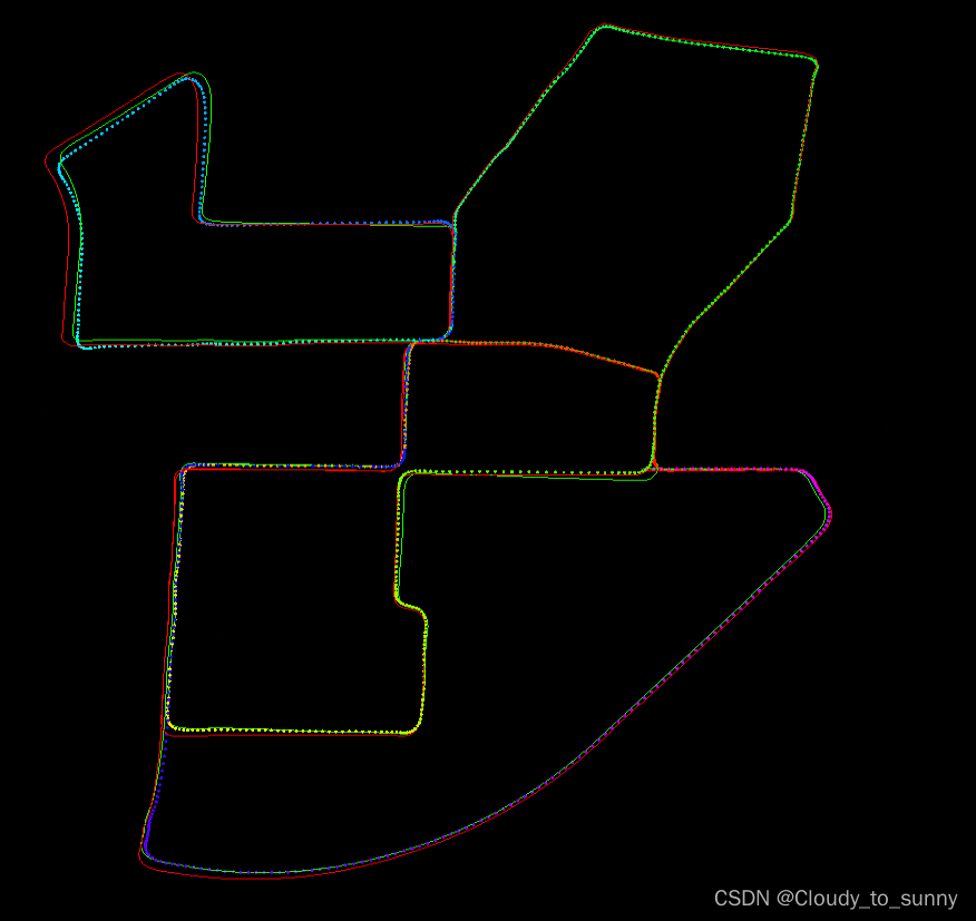
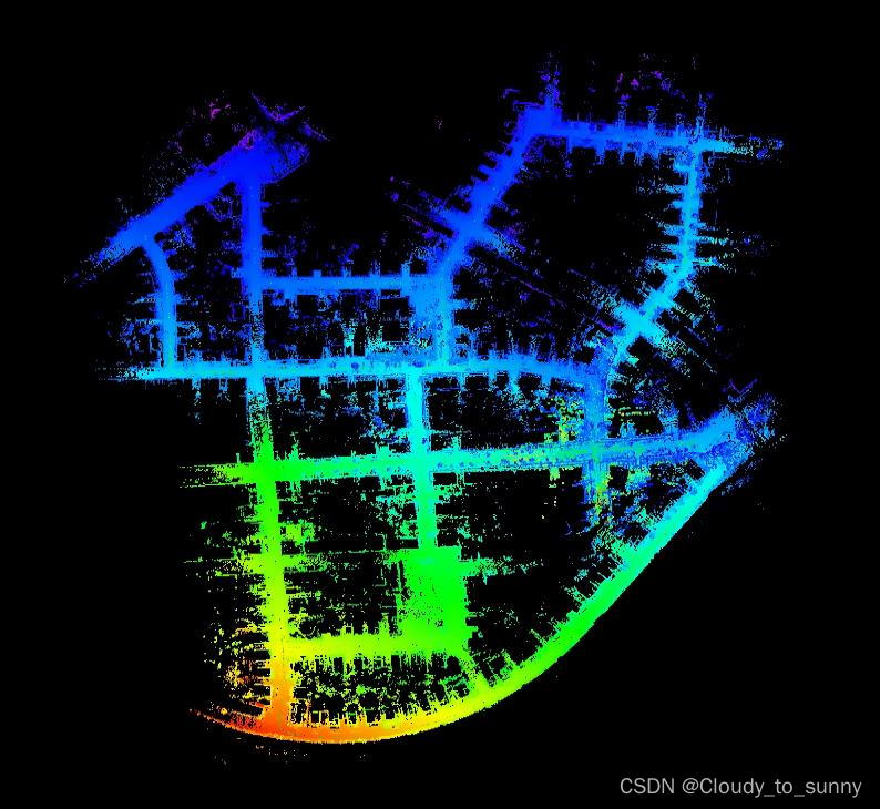
这个图中,绿色的线是实时轨迹,红色的线是真值,五彩的虚线是优化轨迹。rviz中显示实时优化后的轨迹(2023-7-25)
上面已经显示了非回环下的路径,但是回环下的路径是legoloam自带的以点云的形式给出来的,这样就导致我想使用path保存位姿信息时有可能不太方便,因此我就又写了一个实时优化后的轨迹,与自带的不一样的是这个是path不是点云显示:
//定义: ros::Publisher pubLaserAfterMappedPath; nav_msgs::Path laserAfterMappedPath; pubLaserAfterMappedPath = nh.advertise<nav_msgs::Path>("/aft_mapped_path", 5); void publishTF(){ geometry_msgs::Quaternion geoQuat = tf::createQuaternionMsgFromRollPitchYaw (transformAftMapped[2], -transformAftMapped[0], -transformAftMapped[1]); odomAftMapped.header.stamp = ros::Time().fromSec(timeLaserOdometry); odomAftMapped.pose.pose.orientation.x = -geoQuat.y; odomAftMapped.pose.pose.orientation.y = -geoQuat.z; odomAftMapped.pose.pose.orientation.z = geoQuat.x; odomAftMapped.pose.pose.orientation.w = geoQuat.w; odomAftMapped.pose.pose.position.x = transformAftMapped[3]; odomAftMapped.pose.pose.position.y = transformAftMapped[4]; odomAftMapped.pose.pose.position.z = transformAftMapped[5]; odomAftMapped.twist.twist.angular.x = transformBefMapped[0]; odomAftMapped.twist.twist.angular.y = transformBefMapped[1]; odomAftMapped.twist.twist.angular.z = transformBefMapped[2]; odomAftMapped.twist.twist.linear.x = transformBefMapped[3]; odomAftMapped.twist.twist.linear.y = transformBefMapped[4]; odomAftMapped.twist.twist.linear.z = transformBefMapped[5]; pubOdomAftMapped.publish(odomAftMapped); aftMappedTrans.stamp_ = ros::Time().fromSec(timeLaserOdometry); aftMappedTrans.setRotation(tf::Quaternion(-geoQuat.y, -geoQuat.z, geoQuat.x, geoQuat.w)); aftMappedTrans.setOrigin(tf::Vector3(transformAftMapped[3], transformAftMapped[4], transformAftMapped[5])); tfBroadcaster.sendTransform(aftMappedTrans); geometry_msgs::PoseStamped laserAfterMappedPose; laserAfterMappedPose.header.stamp = ros::Time().fromSec(timeLaserOdometry); laserAfterMappedPose.pose = odomAftMapped.pose.pose; laserAfterMappedPath.header.stamp = ros::Time().fromSec(timeLaserOdometry); laserAfterMappedPath.header.frame_id = "/camera_init"; laserAfterMappedPath.poses.push_back(laserAfterMappedPose); pubLaserAfterMappedPath.publish(laserAfterMappedPath); }- 1
- 2
- 3
- 4
- 5
- 6
- 7
- 8
- 9
- 10
- 11
- 12
- 13
- 14
- 15
- 16
- 17
- 18
- 19
- 20
- 21
- 22
- 23
- 24
- 25
- 26
- 27
- 28
- 29
- 30
- 31
- 32
- 33
- 34
- 35
- 36
- 37
- 38
- 39
//定义: bool first_loop; void correctPoses(){ if (aLoopIsClosed == true){ recentCornerCloudKeyFrames. clear(); recentSurfCloudKeyFrames. clear(); recentOutlierCloudKeyFrames.clear(); // update key poses // std::cout << "AGOcloudKeyPoses3D" << cloudKeyPoses3D->points.size() << std::endl; // std::cout << "AGOlaserAfterMappedPath" << laserAfterMappedPath.poses.size() << std::endl; int numPoses = isamCurrentEstimate.size(); for (int i = 0; i < numPoses; ++i){ cloudKeyPoses3D->points[i].x = isamCurrentEstimate.at<Pose3>(i).translation().y(); cloudKeyPoses3D->points[i].y = isamCurrentEstimate.at<Pose3>(i).translation().z(); cloudKeyPoses3D->points[i].z = isamCurrentEstimate.at<Pose3>(i).translation().x(); cloudKeyPoses6D->points[i].x = cloudKeyPoses3D->points[i].x; cloudKeyPoses6D->points[i].y = cloudKeyPoses3D->points[i].y; cloudKeyPoses6D->points[i].z = cloudKeyPoses3D->points[i].z; cloudKeyPoses6D->points[i].roll = isamCurrentEstimate.at<Pose3>(i).rotation().pitch(); cloudKeyPoses6D->points[i].pitch = isamCurrentEstimate.at<Pose3>(i).rotation().yaw(); cloudKeyPoses6D->points[i].yaw = isamCurrentEstimate.at<Pose3>(i).rotation().roll(); // 将欧拉角转换为四元数 Eigen::AngleAxisf roll123(cloudKeyPoses6D->points[i].roll, Eigen::Vector3f::UnitX()); Eigen::AngleAxisf pitch123(cloudKeyPoses6D->points[i].pitch, Eigen::Vector3f::UnitY()); Eigen::AngleAxisf yaw123(cloudKeyPoses6D->points[i].yaw, Eigen::Vector3f::UnitZ()); Eigen::Quaternionf quater; quater = yaw123 * pitch123 * roll123;//完成转换 laserAfterMappedPath.poses[i].pose.position.x = cloudKeyPoses3D->points[i].x; laserAfterMappedPath.poses[i].pose.position.y = cloudKeyPoses3D->points[i].y; laserAfterMappedPath.poses[i].pose.position.z = cloudKeyPoses3D->points[i].z; laserAfterMappedPath.poses[i].pose.orientation.x = quater.x(); laserAfterMappedPath.poses[i].pose.orientation.y = quater.y(); laserAfterMappedPath.poses[i].pose.orientation.z = quater.z(); laserAfterMappedPath.poses[i].pose.orientation.w = quater.w(); } if(first_loop){ laserAfterMappedPath.poses.pop_back(); laserAfterMappedPath.poses.pop_back(); laserAfterMappedPath.poses.pop_back(); laserAfterMappedPath.poses.pop_back(); first_loop = false; } // std::cout << "cloudKeyPoses3D" << cloudKeyPoses3D->points.size() << std::endl; // std::cout << "laserAfterMappedPath" << laserAfterMappedPath.poses.size() << std::endl; aLoopIsClosed = false; } }- 1
- 2
- 3
- 4
- 5
- 6
- 7
- 8
- 9
- 10
- 11
- 12
- 13
- 14
- 15
- 16
- 17
- 18
- 19
- 20
- 21
- 22
- 23
- 24
- 25
- 26
- 27
- 28
- 29
- 30
- 31
- 32
- 33
- 34
- 35
- 36
- 37
- 38
- 39
- 40
- 41
- 42
- 43
- 44
- 45
- 46
- 47
- 48
- 49
- 50
- 51
- 52
- 53
evo 评估
evo开源代码:https://github.com/MichaelGrupp/evo
evo 对姿态的数据格式有三种,分别为:TUM/EuRoC/Kitti
区别为:

也可以看官方的数据格式说明:https://github.com/MichaelGrupp/evo/wiki/Formats

在上边的修改1那里,增加的输出位姿信息,其输出的格式为kitti格式即SE(3),而真值的格式也是kitti。当我使用输出的这个re_00.txt或者re_00_loop.txt与00.txt(真值)做对比时,问题出来了,能够使用evo_traj命令画图,但是当要计算绝对位姿误差时,就出现了问题:(evo命令的使用可以参考如何使用evo工具评估LeGO-LOAM跑KITTI数据集的结果、一种SLAM精度评定工具——EVO使用方法详解、用evo工具评估SLAM轨迹、SLAM精度测评——EVO等)


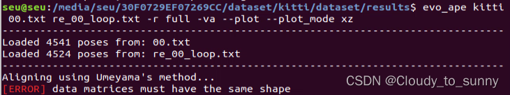
意思是位姿数量不对应,即真值里面的位姿为4541个,而生成的只有4524个。所以报错了。本来我想的是 直接在re_00_loop.txt里面把真值的最后17行添加进去,这样确实能运行了,不报错了。当我想把真值的最后17个数据删掉来跟我的输出位姿对应时,发现这样做会报错,难道它发现我动真值的数据了?哈哈。
这样做的话我意识到一个问题,他们这些位姿是怎么对齐的,并且kitti里面又没有时间戳。因此参考网上的这里,于是乎我想到了解决方法,就是将真值的kitti格式转换成TUM格式,这个格式是带时间戳的。然后自行修改kitti-lego-loam里面的代码生成TUM格式的位姿。这样子 即使数量不对应依旧可以进行计算绝对位姿误差(因为带有时间戳了)将kitti真值转换成TUM格式
准备文件:序列真值轨迹+序列times文件,如00.txt和00序列的times.txt(位于sequences/00/文件夹中)
采用工具:evo中自带的转换程序,evo中contrib文件夹下的kitti_poses_and_timestamps_to_trajectory.py(源码里面才会有,源码在这里)
终端命令:
python kitti_poses_and_timestamps_to_trajectory.py results/00.txt sequences/00/times.txt results/tum_00_gt.txt- 1
转换后的格式打开看一眼是8列,顺序为timestamp x y z q_x q_y q_z q_w
kitti-lego-loam输出TUM格式位姿
最开始,我是在修改1那里直接进行的修改,输出位姿信息,修改如下:
//在transformFusion.cpp里面的laserOdometryHandler函数里面line241左右 /added, cout results/// Eigen::Quaterniond q; q.w()=laserOdometry2.pose.pose.orientation.w; q.x()=laserOdometry2.pose.pose.orientation.x; q.y()=laserOdometry2.pose.pose.orientation.y; q.z()=laserOdometry2.pose.pose.orientation.z; /生成TUM格式位姿///需要增加的部分 std::ofstream foutTum("/home/seu/wsh/study/study/re_00_tum.txt", std::ios::app); foutTum.setf(std::ios::scientific, std::ios::floatfield); foutTum.precision(6); //foutTum << fixed; foutTum << laserOdometry2.header.stamp << " " << laserOdometry2.pose.pose.position.x << " " << laserOdometry2.pose.pose.position.y << " " << laserOdometry2.pose.pose.position.z << " " << q.x() << " " << q.y() << " " << q.z() << " " << q.w() << endl; foutTum.close(); /生成TUM格式位姿结束/需要增加的部分 Eigen::Matrix3d R = q.toRotationMatrix(); if (init_flag==true) { H_init<< R.row(0)[0],R.row(0)[1],R.row(0)[2],transformMapped[3], R.row(1)[0],R.row(1)[1],R.row(1)[2],transformMapped[4], R.row(2)[0],R.row(2)[1],R.row(2)[2],transformMapped[5], 0,0,0,1; init_flag=false; std::cout<<"surf_th : "<<surfThreshold<<endl; }- 1
- 2
- 3
- 4
- 5
- 6
- 7
- 8
- 9
- 10
- 11
- 12
- 13
- 14
- 15
- 16
- 17
- 18
- 19
- 20
- 21
- 22
- 23
- 24
- 25
- 26
- 27
- 28
- 29
- 30
- 31
- 32
- 33
- 34
- 35
这个之间的部分为增加的部分
但是注意到这个输出的是实时位姿,并不是优化后的位姿,因为这个输出是一直在输出,而优化后的输出应该跑完整个过程再输出(因为最后可能有回环,会调整之前的位姿),因此这里只是简单的增加一个输出,下面增加一个优化后的位姿输出,然后一会我们把这两种位姿都计算一下绝对位姿误差就看出来了。参考LeGo-LOAM运行KITTI数据集
增加优化后的位姿输出TUM格式:
//在mapOptmization.cpp文件里面的visualizeGlobalMapThread函数里面进行增加 void visualizeGlobalMapThread(){ ros::Rate rate(0.2); while (ros::ok()){ rate.sleep(); publishGlobalMap(); } // save final point cloud //生成优化后的TUM位姿/// std::cout << "start save final point cloud" << std::endl; std::cout << "======================================================" << std::endl; ofstream foutTUM; foutTUM.open("/home/seu/wsh/study/study/re_00_TUM.txt"); foutTUM << fixed; for(size_t i = 0;i < cloudKeyPoses3D->size();i++) { float cy = cos((cloudKeyPoses6D->points[i].yaw)*0.5); float sy = sin((cloudKeyPoses6D->points[i].yaw)*0.5); float cr = cos((cloudKeyPoses6D->points[i].roll)*0.5); float sr = sin((cloudKeyPoses6D->points[i].roll)*0.5); float cp = cos((cloudKeyPoses6D->points[i].pitch)*0.5); float sp = sin((cloudKeyPoses6D->points[i].pitch)*0.5); float w = cy * cp * cr + sy * sp * sr; float x = cy * cp * sr - sy * sp * cr; float y = sy * cp * sr + cy * sp * cr; float z = sy * cp * cr - cy * sp * sr; //save the traj foutTUM << setprecision(6) << cloudKeyPoses6D->points[i].time << " " << setprecision(9) << cloudKeyPoses6D->points[i].x << " " << cloudKeyPoses6D->points[i].y << " " << cloudKeyPoses6D->points[i].z << " " << x << " " << y << " " << z << " " << w << endl; } foutTUM.close(); 生成优化后的TUM位姿 pcl::io::savePCDFileASCII(+"finalCloud.pcd", *globalMapKeyFramesDS); string cornerMapString = "/tmp/cornerMap.pcd"; string surfaceMapString = "/tmp/surfaceMap.pcd"; string trajectoryString = "/tmp/trajectory.pcd";- 1
- 2
- 3
- 4
- 5
- 6
- 7
- 8
- 9
- 10
- 11
- 12
- 13
- 14
- 15
- 16
- 17
- 18
- 19
- 20
- 21
- 22
- 23
- 24
- 25
- 26
- 27
- 28
- 29
- 30
- 31
- 32
- 33
- 34
- 35
- 36
- 37
- 38
- 39
- 40
这个代码不会一直运行,只会最后,当你在kitti-lego-loam运行终端里按一次Ctrl + C时才会执行。按两次会保存不全,因此按一次就可以了。生成完后会自动停止。

re_00.txt为kitti格式位姿
re_00_tum.txt为tum格式实时位姿
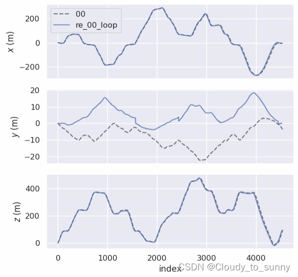
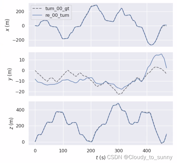
re_00_TUM.txt为tum格式优化位姿re_00_tum.txt轨迹图:
evo_traj tum --ref=tum_00_gt.txt re_00_tum.txt -va --plot --plot_mode xz- 1


re_00_TUM.txt轨迹图:
evo_traj tum --ref=tum_00_gt.txt re_00_TUM.txt -va --plot --plot_mode xz- 1


我们计算一下re_00_tum.txt绝对位姿误差:
(另外说一下,我安装完evo后需要在python3.6的环境下运行,不然会报错,计算完绝对误差之后,在换回2.7,因为其他的比如catkin_make需要2.7环境)


re_00_TUM.txt绝对位姿误差:

可以看到基本上一样,这是为什么呢,因为这是没有添加回环的位姿,所以两条曲线基本一样,然后我们测一下加回环的绝对位姿误差:

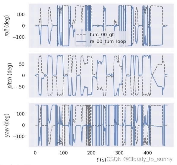
re_00_tum_loop.txt轨迹图:evo_traj tum --ref=tum_00_gt.txt re_00_tum_loop.txt -va --plot --plot_mode xz- 1


re_00_TUM_loop.txt轨迹图:
evo_traj tum --ref=tum_00_gt.txt re_00_TUM_loop.txt -va --plot --plot_mode xz- 1


re_00_tum_loop.txt绝对位姿误差:
evo_ape tum tum_00_gt.txt re_00_tum_loop.txt -r full -va --plot --plot_mode xz- 1


从最后的图看到每到回环的时候,误差就会大,因为优化位姿回环了,实时位姿直接靠了上去,产生了较大误差。
re_00_TUM_loop.txt绝对位姿误差:
evo_ape tum tum_00_gt.txt re_00_TUM_loop.txt -r full -va --plot --plot_mode xz- 1


综合考虑,优化位姿加回环是误差最小的情况,不得不说lego-loam是🐂🍺的。
好了,这次学习就到这里!希望能对大家有所帮助。
参考
1.如何使用evo工具评估LeGO-LOAM跑KITTI数据集的结果
2.使用LeGO-LOAM运行KITTI数据集
3.LeGo-LOAM运行KITTI数据集
4.kitti-lego-loam
5.LeGO-LOAM运行kitti数据集
6.evo
7.使用evo及kitti_odometry_evaluation测评slam轨迹
8.一种SLAM精度评定工具——EVO使用方法详解
9.用evo工具评估SLAM轨迹
10.SLAM精度测评——EVO
11.大文件rosbag播放太慢问题解决
12.kitti真值轨迹由kitti格式转为tum格式
13.KITTI数据集基准、转换成tum以及十个groundtruth对应图
14.rosbag中–clock的使用
15.使用自己的激光雷达/数据集运行lego_loam,修改代码教程 -
相关阅读:
爬虫数据采集:探秘网络数据的捕获之道
【pen200-lab】10.11.1.146
GitHub 曝出漏洞,或导致 4000 多个存储库遭受劫持攻击
Marvelous designer 里为什么衣服不跟着模特运动
定时任务与线程休眠方式比较
iPhone 15 与 iPhone 14:如何选择?
DDD实战(一):如何设计分层架构?
Kubernetes 排错 HTTP
python+vue在线学习教育平台django+flask
[思维]Yet Another Problem Codeforces1747D
- 原文地址:https://blog.csdn.net/weixin_41756645/article/details/126703517
