-
【数电】【verilog】加法器
1.2输入1bit半加器
半加器的电路如下图所示:


- module half adder(
- input wire A,
- input wire B,
- output wire C,
- output wire sum
- );
- //assign sum = (A == B) ? 0 : 1; //这两种方式都可以实现
- assign sum = A^B;
- assign C= A&B;
- endmodule
2.2输入1bit全加器
真值表:
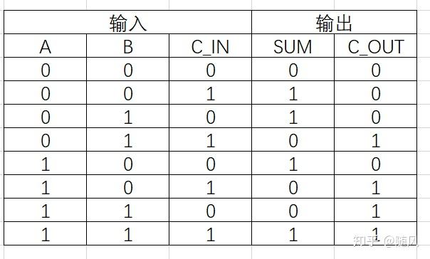
电路图(有很多不同的电路形式):

第一种,利用连续赋值语句实现:
- module full_add2
- (
- input a, //加数
- input b, //被加数
- input cin, //进位输入
- output sum, //结果输出
- output cout //进位输出
- );
- assign sum = a^b^cin;
- assign cout = (a&b)|((a^b)&cin);
- endmodule
第二种,利用行为描述方式实现:
- module full_add2
- (
- input a, //加数
- input b, //被加数
- input cin, //进位输入
- output sum, //结果输出
- output cout //进位输出
- );
- assign {cout,sum} = a+b+cin; //利用拼接的方式实现全加器
- endmodule
第三种,利用两个一位半加器并联实现一个一位全加器,sum = a^b^cin,cout = (a&b)|((a^b)&cin):

- module add_half(
- input A ,
- input B ,
- output wire S ,
- output wire C
- );
- assign S = A ^ B;
- assign C = A & B;
- endmodule
- /***************************************************************/
- module add_full(
- input A ,
- input B ,
- input Ci ,
- output wire S ,
- output wire Co
- );
- wire [1:0] s, c;
- add_half m1 (
- .A(A),
- .B(B),
- .S(s[0]),
- .C(c[0]));
- add_half m2 (
- .A(s[0]),
- .B(Ci),
- .S(s[1]),
- .C(c[1]));
- assign S = s[1];
- assign Co = c[0] | c[1];
- endmodule
3.4位串行加法器(全加器)

第一种,利用半加器生成全加器,再用全加器生成串行全加器:
- `timescale 1ns/1ns
- module add_half(
- input A ,
- input B ,
- output wire S ,
- output wire C
- );
- assign S = A ^ B;
- assign C = A & B;
- endmodule
- /***************************************************************/
- module add_full(
- input A ,
- input B ,
- input Ci ,
- output wire S ,
- output wire Co
- );
- wire c_1;
- wire c_2;
- wire sum_1;
- add_half add_half_1(
- .A (A),
- .B (B),
- .S (sum_1),
- .C (c_1)
- );
- add_half add_half_2(
- .A (sum_1),
- .B (Ci),
- .S (S),
- .C (c_2)
- );
- assign Co = c_1 | c_2;
- endmodule
- /******************************************************************/
- module add_4(
- input [3:0] A ,
- input [3:0] B ,
- input Ci ,
- output wire [3:0] S ,
- output wire Co
- );
- wire [3:0] C;
- add_full u1(
- .A (A[0]),
- .B (B[0]),
- .Ci (Ci),
- .S (S[0]),
- .Co (C[0])
- );
- add_full u2(
- .A (A[1]),
- .B (B[1]),
- .Ci (C[0]),
- .S (S[1]),
- .Co (C[1])
- );
- add_full u3(
- .A (A[2]),
- .B (B[2]),
- .Ci (C[1]),
- .S (S[2]),
- .Co (C[2])
- );
- add_full u4(
- .A (A[3]),
- .B (B[3]),
- .Ci (C[2]),
- .S (S[3]),
- .Co (C[3])
- );
- assign Co = C[3];
- endmodule
第二种,利用拼接的方式来搭建电路:
- //4位全加器,有低位向本位进位(即有输入进位)
- module four_bits_full_add(
- input [3:0]a,b,
- input cin,
- output cout,
- output [3:0]sum
- );
- assign {cout,sum} = a + b + cin;
- endmodule
串行全加器是上面这样,但是这种结构的缺点是,必须要等到上一片的结果算出来之后下一片才能进行工作,当级数很高的时候计算的时间将是每一片时间的n倍,会出现组合逻辑延时过长的问题。此时另一种进位方法——超前进位加法器就可以解决这一延时过高的问题。
4.4位超前进位加法器
根据上面的讲解,我们可以得到:

然后根据下面公式:

带入到上面,得到:

我们定义下面两个式子分别为进位传输函数和进位产生函数:

代入可以得到:

最后,4位的超前进位加法器可以得到下面这些式子:

这里实在看不懂可以翻一番数电的超前进位加法器的内容。
verilog代码如下:0
- module four_bits_fast_adder(cout,sum,a,b,cin);
- output [3:0]sum; //数据累加和本位
- output cout; //输出进位
- input [3:0]a,b; //需要相加的数
- input cin; //输入进位
- wire [4:0]g,p,c; //分别对应Gi、Pi和Ci
- assign c[0] = cin; //最低进位为输入进位
- assign P = a | b; // Pi = Ai·Bi
- assign g = a & b; // Gi = Ai+Bi
- assign c[1] = g[0] | (p[0]&c[0]);
- assign c[2] = g[1] | ( p[1]&(g[0] | (p[0]&c[0]) );
- assign c[3] = g[2] | (p[2]&(g[1]|(p[1]&(g[0]|(p[0]&c[0])))));
- assign c[4] = g[3] | (p[3]&(g[2]|(p[2]&(g[1]|(p[1]&(g[0]|(p[0]&c[0])))))));
- assign sum = p ^ c[3:0];
- assign cout = c[4];
- endmodule
超前进位加法器就是用电路的复杂度来换时间。
-
相关阅读:
单图像超分辨率重建总结
使用x64dbg手动脱UPX壳(UPX4.1.0)
启动Docker Desktop报 “Docker Desktop - Unexpected WSL error”
扫雷(C语言)
MFC Windows 程序设计[340]之特效按钮的实现(附源码)
【限定词习题】another / other / others
asp.net core之HttpClient
SpringSecurity-基于Web的认证与权限访问
2023年电工杯 | 2023年电工杯数学建模数学建模竞赛思路(A题、B题)
2022年下半年 软件设计师 上午试卷(41题—75题)
- 原文地址:https://blog.csdn.net/qq_22774445/article/details/126257315
