-
【全志T113-S3_100ask】10-使用内核驱动点灯(控制继电器)
背景
开发板上没有led灯,且没用其他引出的GPIO,所以就借rgb屏幕的引脚来点个灯(不过分吧@狗头),实现控制继电器。
(一)寻找合适的GPIO
看了好久的原理图,怕与其他功能冲突,所以就使用了 PD13 作为本次实验的引脚。
该引脚除了作为rgb屏幕的功能外,好像没其他作用了,好,就它了。

(二)跳线
焊接飞线接到继电器上。

(三)修改设备树
参考开发文档
Documentation/devicetree/bindings/leds/leds-gpio.txtLEDs connected to GPIO lines Required properties: - compatible : should be "gpio-leds". Each LED is represented as a sub-node of the gpio-leds device. Each node's name represents the name of the corresponding LED. LED sub-node properties: - gpios : Should specify the LED's GPIO, see "gpios property" in Documentation/devicetree/bindings/gpio/gpio.txt. Active low LEDs should be indicated using flags in the GPIO specifier. - function : (optional) see Documentation/devicetree/bindings/leds/common.txt - color : (optional) see Documentation/devicetree/bindings/leds/common.txt - label : (optional) see Documentation/devicetree/bindings/leds/common.txt (deprecated) - linux,default-trigger : (optional) see Documentation/devicetree/bindings/leds/common.txt - default-state: (optional) The initial state of the LED. see Documentation/devicetree/bindings/leds/common.txt - retain-state-suspended: (optional) The suspend state can be retained.Such as charge-led gpio. - retain-state-shutdown: (optional) Retain the state of the LED on shutdown. Useful in BMC systems, for example when the BMC is rebooted while the host remains up. - panic-indicator : (optional) see Documentation/devicetree/bindings/leds/common.txt Examples: #include#include leds { compatible = "gpio-leds"; led0 { gpios = <&mcu_pio 0 GPIO_ACTIVE_LOW>; linux,default-trigger = "disk-activity"; function = LED_FUNCTION_DISK; }; led1 { gpios = <&mcu_pio 1 GPIO_ACTIVE_HIGH>; /* Keep LED on if BIOS detected hardware fault */ default-state = "keep"; function = LED_FUNCTION_FAULT; }; }; run-control { compatible = "gpio-leds"; led0 { gpios = <&mpc8572 6 GPIO_ACTIVE_HIGH>; color = <LED_COLOR_ID_RED>; default-state = "off"; }; led1 { gpios = <&mpc8572 7 GPIO_ACTIVE_HIGH>; color = <LED_COLOR_ID_GREEN>; default-state = "on"; }; }; leds { compatible = "gpio-leds"; led0 { gpios = <&gpio1 2 GPIO_ACTIVE_HIGH>; linux,default-trigger = "max8903-charger-charging"; retain-state-suspended; function = LED_FUNCTION_CHARGE; }; }; - 1
- 2
- 3
- 4
- 5
- 6
- 7
- 8
- 9
- 10
- 11
- 12
- 13
- 14
- 15
- 16
- 17
- 18
- 19
- 20
- 21
- 22
- 23
- 24
- 25
- 26
- 27
- 28
- 29
- 30
- 31
- 32
- 33
- 34
- 35
- 36
- 37
- 38
- 39
- 40
- 41
- 42
- 43
- 44
- 45
- 46
- 47
- 48
- 49
- 50
- 51
- 52
- 53
- 54
- 55
- 56
- 57
- 58
- 59
- 60
- 61
- 62
- 63
- 64
- 65
- 66
- 67
- 68
- 69
- 70
- 71
- 72
- 73
- 74
- 75
简单来说就是指定 compatible = “gpio-leds” 就好了
在根节点下添加:dtsleds { compatible = "gpio-leds"; led0 { label = "red"; gpios = <&pio PD 13 GPIO_ACTIVE_HIGH>; default-state = "off"; }; };- 1
- 2
- 3
- 4
- 5
- 6
- 7
- 8
实例:

(四)使能内核的LED驱动
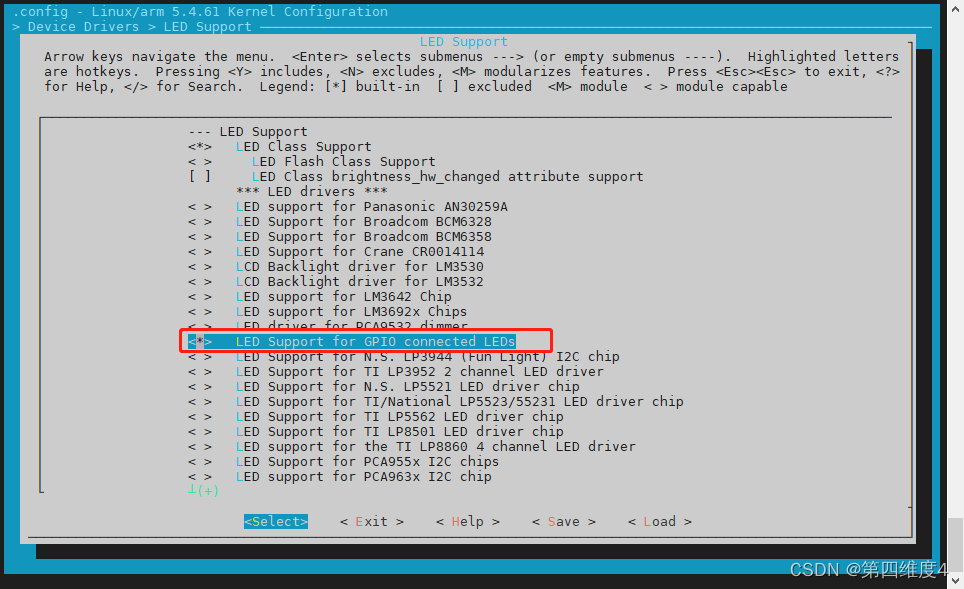
路径参考:Symbol: LEDS_GPIO [=y] │ │ Type : tristate │ │ Prompt: LED Support for GPIO connected LEDs │ │ Location: │ │ -> Device Drivers │ │ -> LED Support (NEW_LEDS [=y]) │ │ Defined at drivers/leds/Kconfig:307 │ │ Depends on: NEW_LEDS [=y] && LEDS_CLASS [=y] && (GPIOLIB [=y] || COMPILE_TEST [=n]) │ │ Selected by [n]: │ │ - PCENGINES_APU2 [=n] && X86 && X86_PLATFORM_DEVICES [=n] && INPUT [=y] && INPUT_KEYBOARD [=y] && \ │ │ GPIOLIB [=y] && LEDS_CLASS [=y]- 1
- 2
- 3
- 4
- 5
- 6
- 7
- 8
- 9
- 10
- 11
然后编译烧写系统。
(五)测试验证
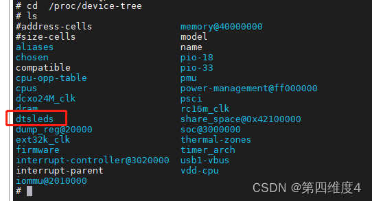
1、寻找设备树,在 /proc/device-tree 下
2、点亮
在 /sys/class/leds/red 下可以找到相关的属性
下面使 brightness 属性为 1 .即可点亮echo 1 > /sys/class/leds/red/brightness- 1
继电器接通!!

关闭的话,使用以下命令即可echo 0 > /sys/class/leds/red/brightness- 1
至此测试完毕
-
相关阅读:
Qt5开发从入门到精通——第十一篇二节(Qt5 事件处理及实例——键盘事件及实例)
EIGRP_协议知识点
Python SQLite3 教程
NFT 作品集推荐|Lululand《爱是永恒》
图鸟使用阿
微信小程序开发缺少中间证书问题(腾讯云、阿里云等做服务器)
快速排序算法
React 第五章 表单
【Codeforces】 CF1762E Tree Sum
智能网络安全网卡|这是不是你要的安全感
- 原文地址:https://blog.csdn.net/qq_46079439/article/details/126131219