-
音频频谱动画的原理与实现(一)
背景
微信的语音消息的按住说话,通过动画反馈出用户输入声音的大小,得到了比较好的效果,增强了用户体验。

微信的录音反馈做的很不错,但并没有表现出音频的频域信息,那么如何表示出声音的频率信息呢?基础知识
音频基础知识可以参考:音频基本概念,下面只列举和本文有关的几个概念。
采样
在信号处理中,采样就是将连续时间的信号减少成离散时间的信号。
声音是一种连续压力波,通过对声音定时采样可以得到计算机能表示离散的数据,采样的频率被称采样率(Sample Rate)。

为了不失真地恢复模拟信号,采样频率应该不小于模拟信号频谱中最高频率的2倍,这个定理被称为采样定理又被称为奈奎斯特采样定理(Nyquist–Shannon sampling theorem)。量化
将采样的结果表示成数据的过程被称为量化,这个数值范围被称为
位深(bit depth)表示数值位数,常见的位数有8bit和16bit,位数越大对信号表达就越精确。响度
声强亦称声强或声强度,反映的是声音的客观物理强弱,决定于发音体振动的振幅,振幅越大,音强越强。
响度(loudness),又称音量,是量度声音大小的知觉量,与声强不同,响度是受主观知觉影响的物理量。在同等声强下,不同频率的声音会造成不同的听觉感知。等响曲线
人类的可听频率范围(20Hz 到 20000Hz)中,由于听觉对 3 000 Hz 左右的声音较为敏感,该段频率也能造成较大的听觉感知。
 等响曲线的横坐标为频率,纵坐标为声压级。在同一条曲线之上,所有频率和声压的组合,都有着一样的响度。
最下方的曲线表示人类能听到的最小的声音响度,即听阈。等响曲线反映了响度听觉的许多特点:- 声压级愈高,响度一般也愈高。
- 响度频率有关,相同声压级的纯音,频率不同,响度也不同。
- 对于不同频率的纯音,提高声压级带来的响度增长,也有所不同。
A计权
在相同声强下,人耳对不同频率音频有不同的音量感受,因此需要对不同频率的音频进行加权,得到对应的音量,从而模拟耳朵的听觉效果。在声音测量中,我们以分贝(dB) 为单位测量声音的响度。

上图横坐标是频率,纵坐标是响度增益。在几种常用的加权曲线中,A权重曲线对低频部分相比其他计权有着最多的衰减,是最常用加权策略。其函数实现为如下,其中f代表频率
傅里叶变换
傅里叶在1807年提出,任何连续周期信号可以由一组适当的正弦曲线组合而成。任何周期函数,都可以看作是不同振幅,不同相位正弦波的叠加。
以其名称命名的傅里叶变换(Fourier transform),是用于信号在时域(或空域)和频域之间的变换。

录音获得的数据都是时域的,横轴是时间,纵轴是信号强度。
频谱动画要求横轴是频域数据,傅里叶变换可以实现时域信息到频域信息的转变。
计算机处理的是离散傅里叶变换(DFT),快速傅里叶变换(FFT)是快速计算离散傅里叶变换(DFT)或其逆变换的方法,它将DFT的复杂度从O(n²)降低到O(nlogn)。
苹果的Accelerate框架中vDSP部分提供了数字信号处理的函数实现,包含FFT,其使用可参考《Real FFT/IFFT with the Accelerate Framework》。
另外关于FFT比较有趣的文章可以看看
《让你永远忘不了的傅里叶变换解析》
《An Interactive Introduction to Fourier Transforms》
《如果看了这篇文章你还不懂傅里叶变换,那就过来掐死我吧》整体流程

要实现对录制声音的频谱动画,将功能分解为以上几个部分,
Recorder实现对音频PCM数据的采集,RealtimeAnalyser对PCM进行频域变换和数据处理,最后由RecordFeedbackView产生反馈动画。iOS音频采集
iOS中实现音频采集的接口有很多,例如
AVAudioRecorder、AudioQueue、AVAudioEngine、AudioUnit。
本文使用AudioQueue实现录音功能,AudioQueue的录音的过程如下:
AudioQueue将麦克风获取的数据填充到AudioQueueBuffer中 ,通过callback函数回调给app,app将AudioQueueBuffer代表的数据消耗后,将AudioQueueBuffer重新入队到AudioQueue中。
使用AudioQueue实现录音的AudioRecorder在github地址:AudioRecorder,简要介绍其中比较关键的部分。初始化Recoder
- (void)start { [[AVAudioSession sharedInstance] setActive:YES error:nil]; [[AVAudioSession sharedInstance] setCategory:AVAudioSessionCategoryPlayAndRecord error:nil]; mAqState.mDataFormat.mSampleRate = self.sampleRate; //采样率, 1s采集的次数 mAqState.mDataFormat.mFormatID = kAudioFormatLinearPCM; //数据格式 PCM mAqState.mDataFormat.mBitsPerChannel = AUDIO_BIT_LEN; //在一个数据帧中,每个通道的样本数据的位数。 mAqState.mDataFormat.mChannelsPerFrame = 1; //每帧数据通道数(左右声道) mAqState.mDataFormat.mFramesPerPacket = 1; //每包数据帧数 mAqState.mDataFormat.mBytesPerFrame = (mAqState.mDataFormat.mBitsPerChannel / 8) * mAqState.mDataFormat.mChannelsPerFrame; mAqState.mDataFormat.mBytesPerPacket = mAqState.mDataFormat.mBytesPerFrame * mAqState.mDataFormat.mFramesPerPacket; mAqState.mDataFormat.mFormatFlags = kLinearPCMFormatFlagIsSignedInteger | kLinearPCMFormatFlagIsPacked; // 上面使用的格式是signed integer类型,后面在做fft计算的时候需要转换成float类型,如果直接使用Float就少了这个过程。 // mAqState.mDataFormat.mFormatFlags = kLinearPCMFormatFlagIsFloat | kLinearPCMFormatFlagIsPacked ; UInt32 frameCount = self.fftSize; mAqState.bufferByteSize = frameCount * (mAqState.mDataFormat.mBitsPerChannel / 8); AudioQueueNewInput(&mAqState.mDataFormat, HandleInputBuffer, (__bridge void *)(self), NULL, kCFRunLoopCommonModes, 0, &mAqState.mQueue); UInt32 channels = 0; UInt32 channelsSize = 0; AudioChannelLayout channelLayout; UInt32 layoutSize = sizeof(channelLayout); AudioQueueGetProperty(mAqState.mQueue, kAudioQueueDeviceProperty_NumberChannels, &channels, &channelsSize); AudioQueueGetProperty(mAqState.mQueue, kAudioQueueProperty_ChannelLayout, &channelLayout, &layoutSize); for (int i = 0; i < kNumberBuffers; i++) { AudioQueueAllocateBuffer(mAqState.mQueue, mAqState.bufferByteSize, &mAqState.mBuffers[i]); AudioQueueEnqueueBuffer(mAqState.mQueue, mAqState.mBuffers[i], 0, NULL); } mAqState.mIsRunning = 1; OSStatus ret = AudioQueueStart(mAqState.mQueue, NULL); }- 1
- 2
- 3
- 4
- 5
- 6
- 7
- 8
- 9
- 10
- 11
- 12
- 13
- 14
- 15
- 16
- 17
- 18
- 19
- 20
- 21
- 22
- 23
- 24
- 25
- 26
- 27
- 28
- 29
- 30
- 31
- 32
- 33
- 34
上面是
AudioQueue的启动代码,
mDataFormat设置了录音的数据格式,其中mFormatID:是音频格式,这里使用LinearPCM;
另外还有采样率(SampleRate)、位深(mBitsPerChannel)、每帧的声道数(mChannelsPerFrame)、packet帧数(mFramesPerPacket)、每帧的字节数(mBytesPerFrame)、Packet字节数(mBytesPerPacket)、数值格式(mFormatFlags)Int or Float等参数的设置,其中Packet、Frame、Sample的关系如下图:

不过本文使用的是单声道,每个packet里面只有一个frame;数据回调
static void HandleInputBuffer(void *inUserData, AudioQueueRef inAudioQueue, AudioQueueBufferRef inBuffer, const AudioTimeStamp *inStartTime, UInt32 inNumPackets, const AudioStreamPacketDescription *inPacketDesc) { AudioRecorder *recorder = (__bridge AudioRecorder *)inUserData; if (recorder == nil) { NSLog(@"recorder is dealloc"); return; } NSTimeInterval recordTime = inStartTime->mSampleTime / recorder->mAqState.mDataFormat.mSampleRate; if (inNumPackets > 0) { [recorder outputPcmBuffer:inBuffer recordTime:recordTime]; } if (recorder->mAqState.mIsRunning) { AudioQueueEnqueueBuffer(recorder->mAqState.mQueue, inBuffer, 0, NULL); } } - (void)outputPcmBuffer:(AudioQueueBufferRef)buffer recordTime:(NSTimeInterval)recordTime { int length = buffer->mAudioDataByteSize / mAqState.mDataFormat.mBytesPerFrame; NSData *data = [NSData dataWithBytes:buffer->mAudioData length:buffer->mAudioDataByteSize]; // 将录制的PCM数据写文件 if (self.outputSteam) { [self.outputSteam write:(uint8_t *)buffer->mAudioData maxLength:buffer->mAudioDataByteSize]; } // 交给分析模块 [self.analyzer onRecievePcmData:data frameCount:length]; }- 1
- 2
- 3
- 4
- 5
- 6
- 7
- 8
- 9
- 10
- 11
- 12
- 13
- 14
- 15
- 16
- 17
- 18
- 19
- 20
- 21
- 22
- 23
- 24
- 25
- 26
- 27
- 28
- 29
- 30
- 31
- 32
- 33
- 34
屏幕绘制的频率是16ms一帧,动画需要16ms更新一下动画数据,我们使用的
SampleRate使用的是16000,所以我们将AudioQueueBuffer对应的FrameCount设置为1024;
当录制的数据填满一个AudioQueueBuffer时,会通过AudioQueueNewInput函数传入的HandleInputBuffer函数将PCM数据回调给RealtimeAnalyser,所以基本每次刷新屏幕都可以获取到最新的频域数据。以上是Recorder部分的全部介绍,这部分总体上比较简单,这里的难点部分主要在RealtimeAnalyser这部分。
RealtimeAnalyser
RealtimeAnalyser的实现我放到了github上,可以点击查看。
数值转换
- (void)onRecievePcmData:(NSData *)rawData frameCount:(UInt32)frameCount { __weak typeof(self) weakSelf = self; dispatch_async(_processQueue, ^{ __strong typeof(weakSelf) strongSelf = weakSelf; float fft_data[frameCount]; short *pcmbuffer = (short *)rawData.bytes; vDSP_vflt16(pcmbuffer, 1, fft_data, 1, frameCount); float scalar = 1.0 / (1 << (AUDIO_BIT_LEN - 1)); vDSP_vsmul(fft_data, 1, &scalar, fft_data, 1, frameCount); [strongSelf writeInput:fft_data audioFrameCount:frameCount]; }); }- 1
- 2
- 3
- 4
- 5
- 6
- 7
- 8
- 9
- 10
- 11
- 12
- 13
- 14
- 15
由于我这里采集的数据格式是
kLinearPCMFormatFlagIsSignedInteger,但是vDSP中处理的数据都是float类型的,所以这里需要对PCM数据的数值格式做转换,直接使用vDSP_vsmul将数值乘以scalar(将数值除以最大值)从而变换为float类型,如果直接使用kLinearPCMFormatFlagIsFloat可以减少这一步。环形缓冲区
录音数据的产生和频域动画的消耗是一个生产-消费模型,中间需要加一个缓冲区进行数据的缓冲。
这里我使用的是环形缓冲区进行数据的缓存,其模型如下图:
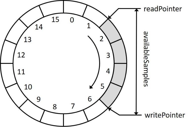
当产生新的录音数据时Write指针前进,当对时域信息进行FFT消耗数据时Read指针也向前移动,达缓冲区的尾部时指针回到缓冲区的起始位置。write和read的实现代码如下- (void)writeInput:(float *)rawData audioFrameCount:(UInt32)framesToProcess { _shouldDoFFTAnalysis = NO; float *dest = _inputBuffer + _circleWriteIndex; float *source = rawData; // Then save the result in the _inputBuffer at the appropriate place. if (_circleWriteIndex + framesToProcess > InputBufferSize) { int length = InputBufferSize - _circleWriteIndex; memcpy(dest, source, sizeof(float) * length); dest = _inputBuffer; source = rawData + length; length = framesToProcess - length; memcpy(dest, source, sizeof(float) * length); _circleWriteIndex = length; } else { memcpy(dest, source, sizeof(float) * framesToProcess); _circleWriteIndex += framesToProcess; if (_circleWriteIndex == InputBufferSize) { _circleWriteIndex = 0; } } _bufferLength += framesToProcess; // A new render quantum has been processed so we should do the FFT analysis again. _shouldDoFFTAnalysis = YES; } - (void)readBufferWithSize:(int)fftSize tempP:(float *)tempP { float *inputBuffer = _inputBuffer; UInt32 tailLength = InputBufferSize - _circleReadIndex; if (tailLength < fftSize) { memcpy(tempP, inputBuffer + _circleReadIndex, sizeof(float) * (tailLength)); memcpy(tempP + tailLength, inputBuffer, sizeof(float) * (fftSize - tailLength)); _circleReadIndex = fftSize - tailLength; } else { memcpy(tempP, inputBuffer + _circleReadIndex, sizeof(float) * fftSize); _circleReadIndex += fftSize; } // 减去被消耗缓冲 _bufferLength -= fftSize; }- 1
- 2
- 3
- 4
- 5
- 6
- 7
- 8
- 9
- 10
- 11
- 12
- 13
- 14
- 15
- 16
- 17
- 18
- 19
- 20
- 21
- 22
- 23
- 24
- 25
- 26
- 27
- 28
- 29
- 30
- 31
- 32
- 33
- 34
- 35
- 36
- 37
- 38
- 39
- 40
- 41
FFT
这里我们使用的是
Accelerate框架中的FFTSetup来实现FFT。1、创建fftSetup
根据
vDSP文档,首先需要定义一个FFT的权重数组(fftSetup),它可以在多次FFT中重复使用和提升FFT性能。_fftSize = fftSize; _log2FFTSize = static_cast<unsigned>(log2(_fftSize)); _fftSetup = vDSP_create_fftsetup(_log2FFTSize, FFT_RADIX2);- 1
- 2
- 3
2、读取时域信号
从环形缓冲区读出需要处理的时域信号数据
// Take the previous fftSize values from the input buffer and copy into the temporary buffer. float *tempP = (float *)malloc(fftSize * sizeof(float)); [self readBufferWithSize:fftSize tempP:tempP];- 1
- 2
- 3
3、加汉宁窗
需要对时域信号加汉宁窗,汉宁窗的创建:
_hannwindow = (Float32 *)malloc(_fftSize * sizeof(Float32)); vDSP_hann_window(_hannwindow, (vDSP_Length)(_fftSize), vDSP_HANN_NORM);- 1
- 2
应用:
// Window the input samples. vDSP_vmul(tempP, 1, _hannwindow, 1, tempP, 1, fftSize);- 1
- 2
加窗主要是为了使信号似乎更好地满足FFT处理的周期性要求,减少泄漏。
这是因为每次FFT只能对有限长度的时域信号进行处理,所以需要对时域信号进行截断,但是可能大部分情况下对周期信号进行的都是非周期性截断(不是周期的整数倍),使得截断后的信号出现泄露。

参考:《怎样用通俗易懂的方式解释窗函数?》《什么是泄漏?》4、转换为复数
vDSP中的离散傅立叶变换函数为了节省内存,提供了一种独特的数据格式,需要将实数转换为复数形式,既是输入也是输出,后面会对这里的原因作出说明。参考《UsingFourierTransforms》int halfSize = fftSize / 2; float value = 0; vDSP_vfill(&value, _frame.imagp, 1, fftSize / 2); vDSP_vfill(&value, _frame.realp, 1, fftSize / 2); vDSP_ctoz(reinterpret_cast<const DSPComplex *>(tempP), 2, &_frame, 1, halfSize); // 释放内存避免泄露 free(tempP);- 1
- 2
- 3
- 4
- 5
- 6
- 7
以下面为例,这里将8个时域信号数据强制转换为
DSPComplex格式的数组,然后通过vDSP_ctoz将其转换为DSPSplitComplex类型的数据。
5、执行FFT
// Perform the FFT via Accelerate // Use FFT forward for standard PCM audio vDSP_fft_zrip(_fftSetup, &_frame, 1, _log2FFTSize, FFT_FORWARD);- 1
- 2
- 3
通过上面的
vDSP_fft_zrip进行FFT计算,这里展开讲一下FFT的输入和输出

实信号的频谱是对称的,所以N位样本数据(N/2位复数)进行FFT计算会得到N/2+1位复数结果。

以上面的信号为例,8个实数换成4个复数后进行FFT计算,产生5个复数:

其中第一个复数是直流分量(DC),最后一个复数是Nyquist频率值(NY),它们的虚部都是0,所以可以将NY的值放到DC中的虚部。

这样就可以使得输入和输出的数据共用同一内存,从而节省内存空间。6、结果缩放
R F i m p = 2 ∗ R F m a t h {RF_{imp} = 2*RF_{math}} RFimp=2∗RFmath
vDSP为了最佳执行速度并不严格遵循傅立叶变换公式,我们必须相应地对得到的结果进行缩放二分之一。7、幅值变换
假设原始信号的峰值为A,那么FFT的结果的每个点(除了第一个点直流分量之外)的模值就是A的 N 2 \frac{N}{2} 2N倍。
第一个点就是直流分量,它的模值就是直流分量的N倍。
这是因为傅里叶级数对应时域幅值,其中已经包含了 1 N \frac{1}{N} N1项,而FFT变换中没有该系数,因此,进行FFT变换后,需除以 N 2 \frac{N}{2} 2N才能与时域对上。
简单来说就是采样求和,加了N次,平均值(直流分量)就得除以N,然后每个频点的“能量”分到了两个共轭的频域参数上,所以是除以N/2// Blow away the packed nyquist component. _frame.imagp[0] = 0; // Normalize so than an input sine wave at 0dBfs registers as 0dBfs (undo FFT scaling factor). // https://blog.csdn.net/seekyong/article/details/104434128 // https://zhuanlan.zhihu.com/p/137433994 当输入样点数据为复数时除以N float magnitudeScale = 2.0 / fftSize; // To provide the best possible execution speeds, the vDSP library's functions don't always adhere strictly // to textbook formulas for Fourier transforms, and must be scaled accordingly. // (See https://developer.apple.com/library/archive/documentation/Performance/Conceptual/vDSP_Programming_Guide/UsingFourierTransforms/UsingFourierTransforms.html#//apple_ref/doc/uid/TP40005147-CH3-SW5) // In the case of a Real forward Transform like above: RFimp = RFmath * 2 so we need to divide the output // by 2 to get the correct value. //http://pkmital.com/home/2011/04/14/real-fftifft-with-the-accelerate-framework/ magnitudeScale = magnitudeScale / 2; vDSP_vsmul(_frame.realp, 1, &magnitudeScale, _frame.realp, 1, halfSize); vDSP_vsmul(_frame.imagp, 1, &magnitudeScale, _frame.imagp, 1, halfSize); vDSP_vfill(&value, _amplitudes, 1, halfSize); //Take the absolute value of the output to get in range of 0 to 1 vDSP_zvabs(&_frame, 1, _amplitudes, 1, halfSize);- 1
- 2
- 3
- 4
- 5
- 6
- 7
- 8
- 9
- 10
- 11
- 12
- 13
- 14
- 15
- 16
- 17
- 18
- 19
- 20
- 21
- 22
- 23
其中的
_amplitudes就是将最终出来的频域数据,对数据进行显示如图

我们录音使用的采样率是16000最大频率为8000HZ,对1024个采样点FFT后产生512个频率点的数据,则每个点代表的频率带宽为8000 / 512 = 15.6hz,每个频率点就是其在各自频率上的振幅。本文参考
https://zhuanlan.zhihu.com/p/137433994
https://blog.csdn.net/seekyong/article/details/104434128
http://pkmital.com/home/2011/04/14/real-fftifft-with-the-accelerate-framework/
https://developer.apple.com/library/archive/documentation/Performance/Conceptual/vDSP_Programming_Guide/UsingFourierTransforms/UsingFourierTransforms.html#//apple_ref/doc/uid/TP40005147-CH3-SW5 -
相关阅读:
在线小说阅读系统
C++中const和constexpr的多文件链接问题
[SWPUCTF-2022-新生赛]ez_sql
Grunt、Gulp 与 webpack:谁更胜一筹?
8、jsp
(2023,GPT-4V,LLM,LMM,功能和应用)大型多模态模型的黎明:GPT-4V(ision) 的初步探索
软件测试中的测试左移与测试右移
2023南华大学计算机考研信息汇总
【开源教程19】疯壳·开源编队无人机-中断(按键检测)
Win32编程串口超时结构体的一般性设置
- 原文地址:https://blog.csdn.net/zhangdongxuan/article/details/126093898
