-
HCIA-综合实验(三)
本篇是关于HCIA的综合项目实验整理笔记。实验拓扑及配置步骤参考资料来自思博教育
1 实验拓扑

2 IP 规划
- R1与ISP相连的网段为101.1.1.0/24
- R2与ISP相连的网段为101.1.2.0/24
- R1与R2相连的网段为192.168.12.0/30
- PC5的地址为172.16.1.1/24网关为172.16.1.254/24;(vlan 172)
- PC1属于Vlan10,ip地址为:192.168.10.1,网关是192.168.10.254/24
- PC2属于Vlan20,ip地址为:192.168.20.1,网关是192.168.20.254/24
- PC3属于Vlan30,IP地址自动获取,网关是192.168.30.254/24;
- R1的loopback0地址为1.1.1.1/32
- R2的loopback0地址为2.2.2.2/32
- SW1的loopback0地址为10.1.1.1/32
- SW4的loopback0地址为10.4.4.4/32
3 实验需求
假设你是SPOTO的网管,为SPOTO上海和福州规划网络。左边蓝色框内为SPOTO福州公司内部网络,右边黄色框内为SPOTO上海公司内部网络,上方模拟ISP网络。
一、福州思博网络规划如下:
a) SW1/2/3组成了福州思博的交换网络,其中SW1是核心层,SW2/3是接入层。
b) 三台交换机上创建vlan10 20 172
c) 交换机之间配置trunk链路,仅允许以上三个vlan通过
d) 交换机使用access链路连接PC,并划入vlan。PC1属于VLAN10, PC2属于VLAN20, PC5模拟网络中的服务器,属于VLAN172
e) 生成树使用STP模式,且SW1为根桥,优先级为0
f) SW1上创建各vlan网关,地址分别是:
vlan10-192.168.10.254/24
vlan20-192.168.20.254/24
vlan172-172.16.1.254/24
g) SW1新建vlan100,并创建vlanif 100 ,IP地址为192.168.2.2/24。配置SW1与R1互联接口,使得SW1可以与R1通信
h) R1与SW1之间运行OSPF,进程号1,RID手动设置为环回口地址
i) 所有network命令均要求使用接口配置掩码的反掩码。SW1环回口通告到区域1,R1环回口通告到区域0
j) 福州网络属于OSPF区域1,并启用区域MD5验证,key-id为1,密码为spoto,且使用display命令无法查看到真实密码
k) 确认所有主机与R1互通
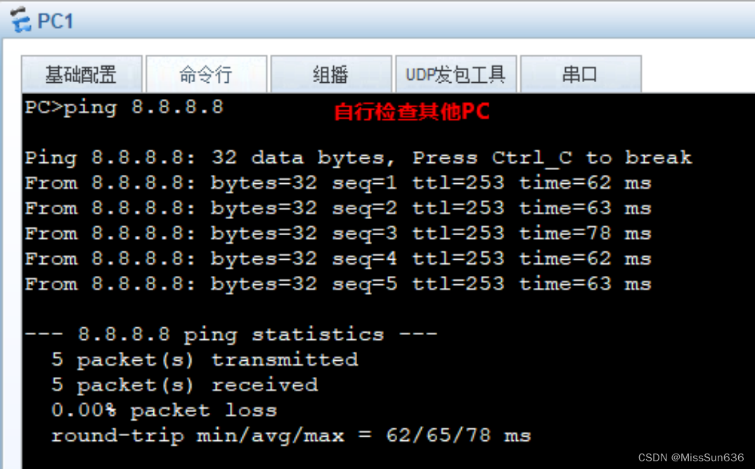
l) R1配置默认路由,用于访问ISP的8.8.8.8
m) R1配置NAT,允许福州网络主机访问外网
n) ACL使用编号2000,规则序号5允许vlan10,规则序号10允许vlan20
o) 内网主机都转换为R1的g0/0/0口IP地址并进行端口转换
p) PC5模拟内网服务器,使用公网地址 101.1.1.111 为外网用户提供各种服务
q) 配置其他必要的路由二、上海思博网络规划如下:
a) SW4组成了上海思博的交换网络
b) 在SW4上创建vlan30
c) SW4使用access链路与PC互联,并划入vlan
d) 在SW4上启用DHCP,为vlan30的主机分配IP地址和网关
e) DHCP使用全局地址池,名称为30,租期为2天
f) 在PC3上确认可以获取IP地址和网关
g) SW4新建vlan100,并创建vlanif 100 ,IP地址为192.168.4.2/24。配置SW4与R2互联接口,使得SW4可以与R2通信
h) R2与SW4之间运行OSPF,进程号1,RID手动设置为环回口地址
i) 所有network命令均要求使用接口配置掩码的反掩码。SW4环回口宣告到区域2,R2环回口宣告到区域0
j) 上海网络属于OSPF区域2,并启用区域MD5验证,key-id为1,密码为spoto,且使用display命令无法查看到真实密码
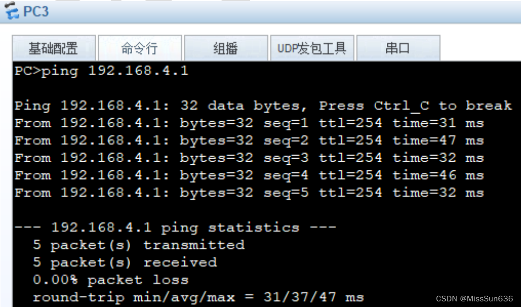
k) 主机可以与R2通信
l) R2配置默认路由,用于访问ISP的8.8.8.8
m) R2配置NAT,允许上海网络主机访问外网
n) ACL使用编号2000,规则序号5允许vlan30
o) 内网主机都转换为R2的g0/0/0口IP地址并进行端口转换
p) 配置其他必要的路由三、福州思博与上海思博网络互联
a) R1与R2之间使用PPP链路互联
b) 配置R1的互联IP地址,注意掩码为30位。R2的互联IP地址由R1分配
c) R1使用AAA管理用户名与密码,用户名为:shanghai,密码为:spoto,服务器类型为PPP。使用display命令无法查看到真实密码
d) R1为认证方,R2为被认证方,使用CHAP验证
e) 确认R1与R2可以通信
f) R1与R2建立OSPF邻居,划入区域0
g) 有network命令均要求使用接口配置掩码的反掩码
h) 启用区域MD5验证,key-id为1,密码为spoto,且使用display命令无法查看到真实密码
i) 确认福州主机可以与上海主机通信四、网络优化
a) 当R2的外网故障时,要求vlan30的主机可以通过PPP链路走R1与外网通信。
b) 在R2上配置适当的路由完成这一需求
c) 在R1上做适当配置完成这一需求
d) 在PC3上ping 8.8.8.8 -t,并关闭R2的G0/0/0接口,确认备用方案有效4 配置思路
4.1 福州思博配置
在 SW1、SW2、SW3 上配置交换网络
SW1
[Huawei] sysname SW1 [SW1] vlan batch 10 20 172 [SW1] interface g0/0/2 [SW1-GigabitEthernet0/0/2] port link-type trunk [SW1-GigabitEthernet0/0/2] port trunk allow-pass vlan 10 20 172 [SW1-GigabitEthernet0/0/2] interface g0/0/3 [SW1-GigabitEthernet0/0/3] port link-type trunk [SW1-GigabitEthernet0/0/3] port trunk allow-pass vlan 10 20 172 [SW1-GigabitEthernet0/0/3] interface g0/0/4 [SW1-GigabitEthernet0/0/4] port link-type access [SW1-GigabitEthernet0/0/3] port default vlan 172- 1
- 2
- 3
- 4
- 5
- 6
- 7
- 8
- 9
- 10
- 11
SW2
[Huawei] sysname SW2 [SW2] vlan batch 10 20 172 [SW2] interface g0/0/2 [SW2-GigabitEthernet0/0/2] port link-type trunk [SW2-GigabitEthernet0/0/2] port trunk allow-pass vlan 10 20 172 [SW2-GigabitEthernet0/0/2] interface g0/0/1 [SW2-GigabitEthernet0/0/1] port link-type trunk [SW2-GigabitEthernet0/0/1] port trunk allow-pass vlan 10 20 172 [SW2-GigabitEthernet0/0/1] interface g0/0/3 [SW2-GigabitEthernet0/0/3] port link-type access [SW2-GigabitEthernet0/0/3] port default vlan 20- 1
- 2
- 3
- 4
- 5
- 6
- 7
- 8
- 9
- 10
- 11
SW3
[Huawei] sysname SW3 [SW3] vlan batch 10 20 172 [SW3] interface g0/0/2 [SW3-GigabitEthernet0/0/2] port link-type trunk [SW3-GigabitEthernet0/0/2] port trunk allow-pass vlan 10 20 172 [SW3-GigabitEthernet0/0/2] interface g0/0/1 [SW3-GigabitEthernet0/0/1] port link-type trunk [SW3-GigabitEthernet0/0/1] port trunk allow-pass vlan 10 20 172 [SW3-GigabitEthernet0/0/1] interface g0/0/3 [SW3-GigabitEthernet0/0/3] port link-type access [SW3-GigabitEthernet0/0/3] port default vlan 10- 1
- 2
- 3
- 4
- 5
- 6
- 7
- 8
- 9
- 10
- 11
SW1、SW2、SW3 运行 STP,且 SW1 为根桥
SW1
[SW1] stp mode stp [SW1] stp priority 0- 1
- 2
SW2
[SW2] stp mode stp- 1
SW3
[SW3] stp mode stp- 1
查看 SW1 的 stp 状态,确保是根桥

SW1 上创建 VLAN 网关
SW1
[SW1] interface vlanif 10 [SW1-Vlanif10] ip address 192.168.10.254 24 [SW1-Vlanif10] interface vlanif 20 [SW1-Vlanif20] ip address 192.168.20.254 24 [SW1-Vlanif20] interface vlanif 172 [SW1-Vlanif172] ip address 172.16.1.254 24- 1
- 2
- 3
- 4
- 5
- 6
SW1、R1 进行配置,使得可以通信
SW1
[SW1] interface loopback 0 [SW1-LoopBack0] ip address 10.1.1.1 32 [SW1] vlan 100 [SW1-vlan100] interface vlanif 100 [SW1-Vlanif100] ip address 192.168.2.2 24 [SW1] interface g0/0/1 [SW1-GigabitEthernet0/0/1] port link-type access [SW1-GigabitEthernet0/0/1] port default vlan 100- 1
- 2
- 3
- 4
- 5
- 6
- 7
- 8
R1
[Huawei] sysname R1 [R1] interface g0/0/1 [R1-GigabitEthernet0/0/1] ip address 192.168.2.1 24 [R1-GigabitEthernet0/0/1] interface loopback 0 [R1-LoopBack0] ip address 1.1.1.1 32- 1
- 2
- 3
- 4
- 5
SW1、R1 配置 OSPF
SW1
[SW1] ospf 1 router-id 10.1.1.1 [SW1-ospf-1] area 1 [SW1-ospf-1-area-0.0.0.1] network 10.1.1.1 0.0.0.0 [SW1-ospf-1-area-0.0.0.1] network 192.168.2.0 0.0.0.255 [SW1-ospf-1-area-0.0.0.1] network 192.168.10.0 0.0.0.255 [SW1-ospf-1-area-0.0.0.1] network 192.168.20.0 0.0.0.255 [SW1-ospf-1-area-0.0.0.1] network 172.16.1.0 0.0.0.255 [SW1-ospf-1-area-0.0.0.1] authentication-mode md5 1 cipher spoto- 1
- 2
- 3
- 4
- 5
- 6
- 7
- 8
R1
[R1] ospf 1 router-id 1.1.1.1 [R1-ospf-1] area 1 [R1-ospf-1-area-0.0.0.1] network 192.168.2.0 0.0.0.255 [R1-ospf-1-area-0.0.0.1] authentication-mode md5 1 cipher spoto- 1
- 2
- 3
- 4
检查 R1 上可以学习到 VLAN10、20、172 的路由,主机能与 R1 互通


ISP 配置相应接口
ISP
[ISP] interface g0/0/0 [ISP-GigabitEthernet0/0/0] ip add 101.1.1.3 24 [ISP-GigabitEthernet0/0/0] interface g0/0/01 [ISP-GigabitEthernet0/0/1] ip address 101.1.2.3 24 [ISP-GigabitEthernet0/0/1] interface loopback 0 [ISP-LoopBack0] ip address 8.8.8.8 32- 1
- 2
- 3
- 4
- 5
- 6
R1、SW1 配置相应接口、默认路由、NAT
SW1
[SW1] ip route-static 0.0.0.0 0.0.0.0 192.168.2.1- 1
R1
[R1] ip route-static 0.0.0.0 0.0.0.0 101.1.1.3 [R1] acl 2000 [R1-acl-basic-2000] rule 5 permit source 192.168.10.0 0.0.0.255 [R1-acl-basic-2000] rule 10 permit source 192.168.20.0 0.0.0.255 [R1] interface g0/0/0 [R1-GigabitEthernet0/0/0] ip add 101.1.1.1 24 [R1-GigabitEthernet0/0/0] nat outbound 2000 [R1-GigabitEthernet0/0/0] nat static global 101.1.1.111 inside 172.16.1.1 netmask 255.255.255.255- 1
- 2
- 3
- 4
- 5
- 6
- 7
- 8
检查 PC 机与 ISP 通信
4.2 上海思博配置
在 SW4 上配置交换网络
SW4
[Huawei] sysname SW4 [SW4] vlan 30 [SW4-vlan30] interface g0/0/2 [SW4-GigabitEthernet0/0/2] port link-type access [SW4-GigabitEthernet0/0/2] port default vlan 30- 1
- 2
- 3
- 4
- 5
在 SW4 上配置 DHCP
SW4
[SW4] interface vlanif 30 [SW4-Vlanif30] ip address 192.168.30.254 24 [SW4] ip pool 30 [SW4-ip-pool-30] gateway-list 192.168.30.254 [SW4-ip-pool-30] network 192.168.30.0 mask 255.255.255.0 [SW4-ip-pool-30] lease day 2 [SW4] interface vlanif 30 [SW4-Vlanif30] dhcp select global- 1
- 2
- 3
- 4
- 5
- 6
- 7
- 8
检查 PC3 可以正常获取地址

SW4、R2 进行配置,使得可以通信
SW4
[SW4] vlan 100 [SW4-vlan100] interface vlanif 100 [SW4-Vlanif100] ip address 192.168.4.2 24 [SW4-Vlanif100] interface g0/0/1 [SW4-GigabitEthernet0/0/1] port link-type access [SW4-GigabitEthernet0/0/1] port default vlan 100 [SW4-GigabitEthernet0/0/1] interface lo 0 [SW4-LoopBack0] ip address 10.4.4.4 32- 1
- 2
- 3
- 4
- 5
- 6
- 7
- 8
R2
[Huawei] sysname R2 [R2] interface g0/0/01 [R2-GigabitEthernet0/0/1] ip address 192.168.4.1 24 [R2-GigabitEthernet0/0/1] interface loopback 0 [R2-LoopBack0] ip address 2.2.2.2 32- 1
- 2
- 3
- 4
- 5
SW4、R4 配置 OSPF
SW4
[SW4] ospf 1 router-id 10.4.4.4 [SW4-ospf-1] area 2 [SW4-ospf-1-area-0.0.0.2] network 192.168.30.0 0.0.0.255 [SW4-ospf-1-area-0.0.0.2] network 10.4.4.4 0.0.0.0 [SW4-ospf-1-area-0.0.0.2] network 192.168.4.0 0.0.0.255 [SW4-ospf-1-area-0.0.0.2] authentication-mode md5 1 cipher spoto- 1
- 2
- 3
- 4
- 5
- 6
R2
[R2] ospf 1 router-id 2.2.2.2 [R2-ospf-1] area 2 [R2-ospf-1-area-0.0.0.2] authentication-mode md5 1 cipher spoto- 1
- 2
- 3
检查 R2 上可以学习到 VLAN30 的路由,主机能与 R2 互通

R2、SW4 配置相应接口、默认路由、NAT
SW4
[SW4] ip route-static 0.0.0.0 0.0.0.0 192.168.4.1- 1
R2
[R2] ip route-static 0.0.0.0 0.0.0.0 101.1.2.3 [R2] acl 2000 [R2-acl-basic-2000] rule 5 permit source 192.168.30.0 0.0.0.255 [R2] interface g0/0/0 [R2-GigabitEthernet0/0/0] ip address 101.1.2.2 24 [R2-GigabitEthernet0/0/0] nat outbound 2000- 1
- 2
- 3
- 4
- 5
- 6
检查 PC 机与 ISP 通信

4.3 配置福州思博与上海思博互联
配置 R1 的 AAA
R1
[R1-aaa] local-user shanghai password cipher spoto [R1-aaa] local-user shanghai service-type ppp- 1
- 2
配置 R1 的 IP,并为 R2 分配地址,采用 CHAP 认证
R1
[R1] interface s1/0/0 [R1-Serial1/0/0] ip address 192.168.12.1 30 [R1-Serial1/0/0] remote address 192.168.12.2 [R1-Serial1/0/0] ppp authentication-mode chap- 1
- 2
- 3
- 4
R2
[R2] interface s1/0/0 [R2-Serial1/0/0] ppp chap user shanghai [R2-Serial1/0/0] ppp chap password cipher spoto [R2-Serial1/0/0] ip address ppp-negotiate- 1
- 2
- 3
- 4
R1、R2 配置 ospf
R1
[R1] ospf 1 [R1-ospf-1] area 0 [R1-ospf-1-area-0.0.0.0] network 1.1.1.1 0.0.0.0 [R1-ospf-1-area-0.0.0.0] network 192.168.12.0 0.0.0.3 [R1-ospf-1-area-0.0.0.0] authentication-mode md5 1 cipher spoto- 1
- 2
- 3
- 4
- 5
R2
[R2] ospf 1 [R1-ospf-1] area 0 [R1-ospf-1-area-0.0.0.0] network 2.2.2.2 0.0.0.0 [R1-ospf-1-area-0.0.0.0] network 192.168.12.0 0.0.0.3 [R1-ospf-1-area-0.0.0.0] authentication-mode md5 1 cipher spoto- 1
- 2
- 3
- 4
- 5
验证 PC1、PC2 能与 PC3 通信

4.4 网络优化
在 R1 和 R2 上配置,实现线路的冗余
R1
[R1] acl 2000 [R1-acl-basic-2000] rule permit source 192.168.30.0 0.0.0.255- 1
- 2
R2
[R2] ip route-static 0.0.0.0 0.0.0.0 192.168.12.1 preference 70- 1
-
相关阅读:
鼠标右键使用VSCode打开文件或文件夹配置
广东海洋大学计算机考研资料汇总
现货白银入门技巧:心理线
C语言:打印100-200的质数
StatefulSet:有状态应用部署
Java#数据结构----2
SpringBatch(9):ItemReader详解
Elasticsearch 安装踩坑!
朝着“强国建设民族复兴”之路奋勇前行
【无标题】接口测试用例设计(精华)
- 原文地址:https://blog.csdn.net/qq_33794290/article/details/134460810