-
全志R128应用开发案例——SPI 驱动 TFT LCD 屏
SPI 驱动 TFT LCD 屏
R128 平台提供了 SPI DBI 的 SPI TFT 接口,具有如下特点:
- Supports DBI Type C 3 Line/4 Line Interface Mode
- upports 2 Data Lane Interface Mode
- Supports data source from CPU or DMA
- Supports RGB111/444/565/666/888 video format
- Maximum resolution of RGB666 240 x 320@30Hz with single data lane
- Maximum resolution of RGB888 240 x 320@60Hz or 320 x 480@30Hz with dual data lane
- Supports tearing effect
- Supports software flexible control video frame rate
同时,提供了SPILCD驱动框架以供 SPI 屏幕使用。
本次使用的是 Dshan_Display Module,如下图:

引脚配置如下:
R128 Devkit TFT 模块 PA12 CS PA13 SCK PA18 MOSI PA9 PWM PA20 RESET PA19 RS 3V3 3.3V GND GND 
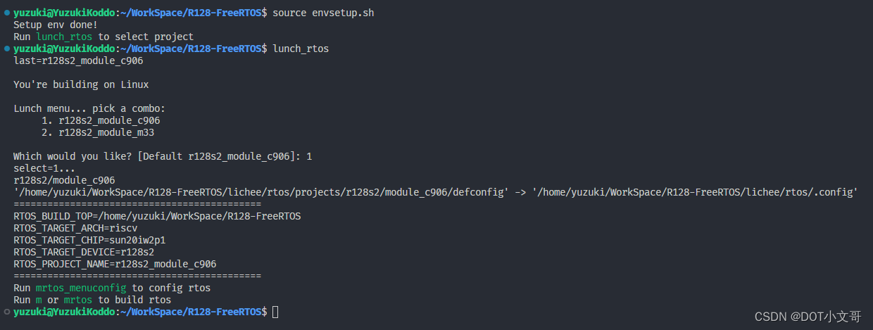
载入方案
我们使用的开发板是 R128-Devkit,需要开发 C906 核心的应用程序,所以载入方案选择
r128s2_module_c906$ source envsetup.sh $ lunch_rtos 1- 1
- 2
设置 SPI 驱动
屏幕使用的是SPI驱动,所以需要勾选SPI驱动,运行
mrtos_menuconfig进入配置页面。前往下列地址找到SPI DevicesDrivers Options ---> soc related device drivers ---> SPI Devices ---> -*- enable spi driver- 1
- 2
- 3
- 4

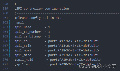
配置 SPI 引脚
打开你喜欢的编辑器,修改文件:
board/r128s2/module/configs/sys_config.fex,在这里我们不需要用到 SPI HOLD与SPI WP引脚,注释掉即可。;---------------------------------------------------------------------------------- ;SPI controller configuration ;---------------------------------------------------------------------------------- ;Please config spi in dts [spi1] spi1_used = 1 spi1_cs_number = 1 spi1_cs_bitmap = 1 spi1_cs0 = port:PA12<6><0><3>spi1_sclk = port:PA13<6><0><3> spi1_mosi = port:PA18<6><0><3> spi1_miso = port:PA21<6><0><3> ;spi1_hold = port:PA19<6><0><2> ;spi1_wp = port:PA20<6><0><2> - 1
- 2
- 3
- 4
- 5
- 6
- 7
- 8
- 9
- 10
- 11
- 12
- 13
- 14
设置 PWM 驱动
屏幕背光使用的是PWM驱动,所以需要勾选PWM驱动,运行
mrtos_menuconfig进入配置页面。前往下列地址找到PWM DevicesDrivers Options ---> soc related device drivers ---> PWM Devices ---> -*- enable pwm driver- 1
- 2
- 3
- 4

配置 PWM 引脚
打开你喜欢的编辑器,修改文件:
board/r128s2/module/configs/sys_config.fex,增加 PWM1 节点[pwm1] pwm_used = 1 pwm_positive = port:PA9<4><0><3>- 1
- 2
- 3

设置 SPI LCD 驱动
SPI LCD 由专门的驱动管理。运行
mrtos_menuconfig进入配置页面。前往下列地址找到SPILCD Devices,注意同时勾选spilcd hal APIs test方便测试使用。Drivers Options ---> soc related device drivers ---> [*] DISP Driver Support(spi_lcd) [*] spilcd hal APIs test- 1
- 2
- 3
- 4

选择驱动的显示屏
在 SPILCD 驱动选择界面可以看到
LCD_FB panels select选择 SPI 屏幕的驱动,本文只注重于 SPI LCD 的使用,驱动编写请查看《SPI LCD 显示驱动》进入
LCD_FB panels select选项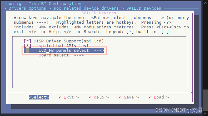
选择并勾选
[*] LCD support JLT35031C panel
配置 SPI LCD 引脚
打开你喜欢的编辑器,修改文件:
board/r128s2/module/configs/sys_config.fexFEX 解析器不支持行尾注释,直接复制需要删除行尾的注释
;---------------------------------------------------------------------------------- ;lcd_fb0 configuration ;---------------------------------------------------------------------------------- [lcd_fb0] lcd_used = 1 ; 使用显示屏 lcd_model_name = "spilcd" ; 模型:spilcd lcd_driver_name = "jlt35031c" ; 屏幕驱动:jlt35031c lcd_x = 320 ; 屏幕宽分辨率 lcd_y = 480 ; 屏幕高分辨率 lcd_width = 49 ; 屏幕物理宽度 lcd_height = 74 ; 屏幕物理高度 lcd_data_speed = 60 ; SPI 驱动频率 60MHz lcd_pwm_used = 1 ; lcd使用pwm背光 lcd_pwm_ch = 1 ; lcd使用pwm背光通道1 lcd_pwm_freq = 5000 ; lcd使用pwm背光频率5000Hz lcd_pwm_pol = 0 ; lcd使用pwm背光相位0 lcd_if = 0 ; lcd使用spi接口,0-spi, 1-dbi lcd_pixel_fmt = 11 ; 以下内容详见 SPILCD 文档 lcd_dbi_fmt = 2 lcd_dbi_clk_mode = 1 lcd_dbi_te = 1 fb_buffer_num = 2 lcd_dbi_if = 4 lcd_rgb_order = 0 lcd_fps = 60 lcd_spi_bus_num = 1 lcd_frm = 2 lcd_gamma_en = 1 lcd_backlight = 100 lcd_power_num = 0 lcd_gpio_regu_num = 0 lcd_bl_percent_num = 0 lcd_spi_dc_pin = port:PA19<1><0><3><0> ; DC脚 ;RESET Pin lcd_gpio_0 = port:PA20<1><0><2><0> ; 复位脚- 1
- 2
- 3
- 4
- 5
- 6
- 7
- 8
- 9
- 10
- 11
- 12
- 13
- 14
- 15
- 16
- 17
- 18
- 19
- 20
- 21
- 22
- 23
- 24
- 25
- 26
- 27
- 28
- 29
- 30
- 31
- 32
- 33
- 34
- 35
- 36
- 37

结果
以上配置完成后,编译打包烧录,上电后屏幕背光亮起,屏幕为黑色。

并且可以在 LOG 中看到
[LCD_FB] lcd_fb_probe,line:103:和spi_clk_init()1609 [spi1] clk rate auto adjust to 48000000SPI 初始化的 LOG。
然后可以用
test_spilcd测试屏幕,日志如下
执行命令之后屏幕会变为黄色。
- SPI 屏幕颜色说明:<SPI LCD 显示驱动 - SPI LCD 颜色相关问题>

test_spilcd代码如下:#include#include #include #include #include #include #include #include #include #include static uint32_t width; static uint32_t height; static long int screensize = 0; static char *fbsmem_start = 0; static void lcdfb_fb_init(uint32_t yoffset, struct fb_info *p_info) { p_info->screen_base = fbsmem_start; p_info->var.xres = width; p_info->var.yres = height; p_info->var.xoffset = 0; p_info->var.yoffset = yoffset; } int show_rgb(unsigned int sel) { int i = 0, ret = -1; struct fb_info fb_info; int bpp = 4; unsigned char color[4] = {0xff,0x0,0xff,0x0}; width = bsp_disp_get_screen_width(sel); height = bsp_disp_get_screen_height(sel); screensize = width * bpp * height; fbsmem_start = hal_malloc_coherent(screensize); hal_log_info("width = %d, height = %d, screensize = %d, fbsmem_start = %x\n", width, height, screensize, fbsmem_start); memset(fbsmem_start, 0, screensize); for (i = 0; i < screensize / bpp; ++i) { memcpy(fbsmem_start+i*bpp, color, bpp); } memset(&fb_info, 0, sizeof(struct fb_info)); lcdfb_fb_init(0, &fb_info); hal_dcache_clean((unsigned long)fbsmem_start, screensize); bsp_disp_lcd_set_layer(sel, &fb_info); hal_free_coherent(fbsmem_start); return ret; } static int cmd_test_spilcd(int argc, char **argv) { uint8_t ret; hal_log_info("Run spilcd hal layer test case\n"); ret = show_rgb(0); hal_log_info("spilcd test finish\n"); return ret; } FINSH_FUNCTION_EXPORT_CMD(cmd_test_spilcd, test_spilcd, spilcd hal APIs tests) - 1
- 2
- 3
- 4
- 5
- 6
- 7
- 8
- 9
- 10
- 11
- 12
- 13
- 14
- 15
- 16
- 17
- 18
- 19
- 20
- 21
- 22
- 23
- 24
- 25
- 26
- 27
- 28
- 29
- 30
- 31
- 32
- 33
- 34
- 35
- 36
- 37
- 38
- 39
- 40
- 41
- 42
- 43
- 44
- 45
- 46
- 47
- 48
- 49
- 50
- 51
- 52
- 53
- 54
- 55
- 56
- 57
- 58
- 59
- 60
- 61
- 62
- 63
- 64
- 65
- 66
- 67
- 68
- 69
- 70
-
相关阅读:
PDF怎么转换成Word文档呢?不妨试试这两种方法!
java毕业生设计中医药科普网站计算机源码+系统+mysql+调试部署+lw
还不懂Java线程池实现原理,看这一篇文章就够了
【JAVA】List
kafka 消费者的消费策略以及再平衡1
jenkins使用注意问题
消费者与生产者问题
C++ 基础与深度分析 Chapter9 序列与关联容器(容器的概述、序列容器)
力扣:72. 编辑距离
C++并发编程 - 同步并发操作
- 原文地址:https://blog.csdn.net/weixin_43094346/article/details/133989304
