-
基于RIP的MGRE实验
目录
题目及视图:

实验要求:
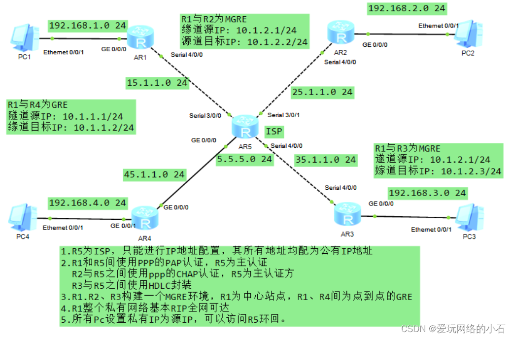
1.R5为ISP,只能进行IP地址配置,其所有地址均配为公有IP地址
2.R1和R5间使用PPP的PAP认证,R5为主认证
R2与R5之间使用ppp的CHAP认证,R5为主认证方
R3与R5之间使用HDLC封装
3.R1.R2、R3构建一个MGRE环境,R1为中心站点,R1、R4间为点到点的GRE
4.R1整个私有网络基本RIP全网可达
5.所有PC设置私有IP为源IP,可以访问R5环回。实验步骤:
第一步:设计思路:
1. 由(1)知:R5 为ISP则在地址规划时,应注意公私网的区分。
2. 配置公网通 使得PC可以访问R5的回环
3.配置PAP CHAP认证以及HDLC封装。
4.构建GRE以及MGRE环境,
5.构建GRE以及MGRE下的RIP环境
6.测试(ping以及抓包)
第二步:搭建拓扑及IP地址的规划
IP地址的规划:
路由器IP地址如拓扑图中所示。
PC地址规划如下:
PC1 192.168.1.2/24 网关 192.168.1.1/24 PC2 192.168.2.2/24 网关 192.168.2.1/24 PC3 192.168.3.2/24 网关 192.168.3.1/24 PC4 192.168.4.2/24 网关 192.168.4.1/24 第三步:配置命令
1. IP地址配置
配置R1:
- <Huawei>system-view
- [Huawei]sy R1
- [R1]int g 0/0/0
- [R1-GigabitEthernet0/0/0]ip add 192.168.1.1 24
- [R1-GigabitEthernet0/0/0]int s 4/0/0
- [R1-Serial4/0/0]ip add 15.1.1.1 24
配置R2:
- <Huawei>system-view
- [Huawei]sy R2
- [R2]INT G 0/0/0
- [R2-GigabitEthernet0/0/0]IP ADD 192.168.2.1 24
- [R2-GigabitEthernet0/0/0]INT s 4/0/0
- [R2-Serial4/0/0]ip add 25.1.1.1 24
配置R3:
- <Huawei>system-view
- [Huawei]sy R3
- [R3]int g 0/0/0
- [R3-GigabitEthernet0/0/0]ip add 192.168.3.1 24
- [R3-GigabitEthernet0/0/0]int s 4/0/0
- [R3-Serial4/0/0]ip add 35.1.1.1 24
配置R4:
- <Huawei>sy
- [Huawei]sy R4
- [R4]int g 0/0/0
- [R4-GigabitEthernet0/0/0]ip add 45.1.1.1 24
- [R4-GigabitEthernet0/0/0]int g 0/0/1
- [R4-GigabitEthernet0/0/1]ip add 192.168.4.1 24
配置R5:
- <Huawei>system-view
- [Huawei]sy R5
- [R5]INT S 3/0/0
- [R5-Serial3/0/0]IP ADD 15.1.1.2 24
- [R5-Serial3/0/0]int s 3/0/1
- [R5-Serial3/0/1]ip add 25.1.1.2 24
- [R5-Serial3/0/1]int s 4/0/0
- [R5-Serial4/0/0]ip add 35.1.1.2 24
- [R5-Serial4/0/0]int g 0/0/0
- [R5-GigabitEthernet0/0/0]ip add 45.1.1.2 24
- [R5-GigabitEthernet0/0/0]q
- [R5]int l 0
- [R5-LoopBack0]ip add 5.5.5.5 24
2.缺省路由配置
- [R1]ip route-static 0.0.0.0 0 15.1.1.2
- [R2]ip route-static 0.0.0.0 0 25.1.1.2
- [R3]ip route-static 0.0.0.0 0 35.1.1.2
- [R4]ip route-static 0.0.0.0 0 45.1.1.2
3.NAT配置
配置R1:
- [R1]acl 2000
- [R1-acl-basic-2000]rule 1 permit source any
- [R1]INT S 4/0/0
- [R1-Serial4/0/0]nat outbound 2000
配置R2:
- [R2]ACL 2000
- [R2-acl-basic-2000]rule 1 permit source any
- [R2-acl-basic-2000]q
- [R2]int s 4/0/0
- [R2-Serial4/0/0]nat outbound 2000
配置R3:
- [R3]acl 2000
- [R3-acl-basic-2000]rule 1 permit source any
- [R3-acl-basic-2000]q
- [R3]int s 4/0/0
- [R3-Serial4/0/0]nat outbound 2000
配置R4:
- [R4]acl 2000
- [R4-acl-basic-2000]rule 1 permit source any
- [R4-acl-basic-2000]q
- [R4]int g 0/0/0
- [R4-GigabitEthernet0/0/0]nat outbound 2000
4. 配置PAP认证
认证方配置
- [R5]aaa # 进入aaa模式
- [R5-aaa]local-user huawei password cipher 123456 # 创建认证端账户huawei,密码为123456
- [R5-aaa]local-user huawei service-type ppp # 此账户只允许被ppp协议使用
- [R5-Serial3/0/0]link-protocol ppp # 串口接口使用ppp协议
- [R5-Serial3/0/0]ppp authentication-mode pap # 启用ppp协议中的pap协议认证
被认证方配置
R1配置
- [R1-Serial4/0/0]link-protocol ppp # 串口接口使用PPP协议
- [R1-Serial4/0/0]ppp pap local-user huawei password cipher 123456
- # 输入认证端账户密码
5. 配置CHAP认证
认证方配置
- [R5]aaa
- [R5-aaa]local-user huawei password cipher 123456
- [R5-aaa]local-user huawie service-type ppp
- [R5-Serial3/0/1]link-protocol ppp
- [R5-Serial3/0/1]ppp authentication-mode chap # 启用ppp协议中的chap协议认证
被认证方配置
- [R2]int s 4/0/0
- [R2-Serial4/0/0]ppp chap user huawie
- [R2-Serial4/0/0]ppp chap password cipher 123456
6. HDLC封装
- [R5]interface Serial 4/0/0
- [R5-Serial4/0/0]link-protocol hdlc
- [R3]int Serial 4/0/0
- [R3-Serial4/0/0]link-protocol hdlc
7. R1R2R3构建MGRE环境
中心站点R1配置:
[R1]display nhrp peer all 查看nhrp注册情况
- [R1]int Tunnel 0/0/0 # 创建隧道口
- [R1-Tunnel0/0/0]ip add 10.1.1.1 24 # 为隧道配置IP地址
- [R1-Tunnel0/0/0]tunnel-protocol gre p2mp # 修改接口模式为多点GRE模式
- [R1-Tunnel0/0/0]source 15.1.1.1 # 定义公有封装源
- [R1-Tunnel0/0/0]nhrp network-id 100 # 创建域ID
分支占点
R2配置
- [R2]int t 0/0/0
- [R2-Tunnel0/0/0]ip add 10.1.1.2 24
- [R2-Tunnel0/0/0]tunnel-protocol gre p2mp
- [R2-Tunnel0/0/0]source S4/0/0 # 假设分支站点的IP地址是不固定的
- [R2-Tunnel0/0/0]nhrp entry 10.1.1.1 15.1.1.1 register # 分支需要到中心站点注册
- # 隧道地址 物理地址 注册
- [R2-Tunnel0/0/0]nhrp network-id 100
R3配置
- [R3]int t 0/0/0
- [R3-Tunnel0/0/0]ip add 10.1.1.3 24
- [R3-Tunnel0/0/0]tunnel-protocol gre p2mp
- [R3-Tunnel0/0/0]source s 4/0/0
- [R3-Tunnel0/0/0]nhrp entry 10.1.1.1 15.1.1.1 register
- [R3-Tunnel0/0/0]nhrp network-id 100
8. 配置GRE
R1配置
- [R1]int t 0/0/1
- [R1-Tunnel0/0/1]ip add 2.1.1.1 24
- [R1-Tunnel0/0/1]tunnel-protocol gre
- [R1-Tunnel0/0/1]source 15.1.1.1
- [R1-Tunnel0/0/1]destination 45.1.1.1
R4配置
- [R4]int t 0/0/1
- [R4-Tunnel0/0/1]ip add 20.1.1.2 24
- [R4-Tunnel0/0/1]tunnel-protocol gre
- [R4-Tunnel0/0/1]source 45.1.1.1
- [R4-Tunnel0/0/1]destination 15.1.1.1
9. 配置RIP路由
MGRE环境下RIP路由配置
R1配置
- [R1]rip 1
- [R1-rip-1]version 2
- [R1-rip-1]undo summary
- [R1-rip-1]network 192.168.1.0
- [R1-rip-1]network 10.0.0.0
注意:MGRE环境下配置RIP的中心站点,需要开启伪⼴播和关闭⽔平分割
- [R1]int t 0/0/0
- [R1-Tunnel0/0/0]nhrp entry multicast dynamic #开启伪广播域
- [R1-Tunnel0/0/0]undo rip split-horizon #关闭水平分割
R2配置
- [R2]rip 1
- [R2-rip-1]version 2
- [R2-rip-1]undo summary
- [R2-rip-1]network 192.168.2.0
- [R2-rip-1]network 10.0.0.0
R3配置
- [R3]rip 1
- [R3-rip-1]version 2
- [R3-rip-1]undo summary
- [R3-rip-1]network 192.168.3.0
- [R3-rip-1]network 10.0.0.0
GRE环境下RIP路由配置
R1配置
- [R1]rip 1
- [R1-rip-1]version 2
- [R1-rip-1]network 20.0.0.0
R4配置
- [R4]rip 1
- [R4-rip-1]version 2
- [R4-rip-1]undo summary
- [R4-rip-1]network 20.0.0.0
- [R4-rip-1]network 192.168.4.0
10. 测试
测试一:用设备PC1去pingPC4
- PC>ping 192.168.4.2
- Ping 192.168.4.2: 32 data bytes, Press Ctrl_C to break
- Request timeout!
- From 192.168.4.2: bytes=32 seq=2 ttl=126 time=31 ms
- From 192.168.4.2: bytes=32 seq=3 ttl=126 time=31 ms
- From 192.168.4.2: bytes=32 seq=4 ttl=126 time=31 ms
- From 192.168.4.2: bytes=32 seq=5 ttl=126 time=32 ms
- --- 192.168.4.2 ping statistics ---
- 5 packet(s) transmitted
- 4 packet(s) received
- 20.00% packet loss
- round-trip min/avg/max = 0/31/32 ms
测试二:用设备PC1去pingPC3
- PC>ping 192.168.3.2
- Ping 192.168.3.2: 32 data bytes, Press Ctrl_C to break
- Request timeout!
- From 192.168.3.2: bytes=32 seq=2 ttl=126 time=31 ms
- From 192.168.3.2: bytes=32 seq=3 ttl=126 time=32 ms
- From 192.168.3.2: bytes=32 seq=4 ttl=126 time=31 ms
- From 192.168.3.2: bytes=32 seq=5 ttl=126 time=16 ms
- --- 192.168.3.2 ping statistics ---
- 5 packet(s) transmitted
- 4 packet(s) received
- 20.00% packet loss
- round-trip min/avg/max = 0/27/32 ms
11.抓包
抓包测试一:抓PC4 的接口

抓包测试二:抓PC3 的接口


-
相关阅读:
【100天精通Python】Day68:Python可视化_Matplotlib 绘制热力图,示例+代码
Google Earth Engine(GEE)——Landsat 全球土地调查 1975年数据集
golang 版本升级
Java——单例模式
详细介绍项目开发中多种常用的分布式锁的实现以及分析比较
中国大陆IP段(含港澳)【2022-08-13】
javaScript贪吃蛇
layui2.9.7-入门初学
水塘抽样(应用场景+算法步骤+算法证明+Python实现)
Pytorch构建Transformer实现英文翻译
- 原文地址:https://blog.csdn.net/2302_77035737/article/details/133965148