-
eNSP网络实验
二层VLAN

四台PC的IP地址如图所示,子网掩码均为255.255.255.0,四台PC处在同一个局域网之中,在配置VLAN之前能够彼此ping通。配置的目的是将PC1和PC3划分到VLAN10中,PC2和PC4划分到VLAN20中。
在配置之前需要进入系统视角。创建VLAN
在两个交换机上都需要分别创建VLAN10和VLAN20:
vlan vlan-id- 1
通过vlan命令创建vlan,vlan-id为指定的id。


配置access接口
按照不同端口类型的功能,两个交换机与PC连接的端口都配置为access。
1.配置接口类型port link-type access- 1
2.配置端口的默认VLAN
port default vlan vlan-id- 1

配置Trunk接口
两个交换机相互连接的端口可能要通过多个vlan,因此设置为Trunk接口。
1.配置接口类型port link-type trunk- 1
2.接口加入允许通过的vlan
port trunk allow-pass vlan vlan-id- 1
3.配置trunk接口的默认vlan(一般默认为1)
port trunk pvid vlan vlan-id- 1


测试
经过上面的配置之后,通过测试可以发现只有在同一vlan下的主机才能相互ping通了,实现了广播域的分割。
MPLS
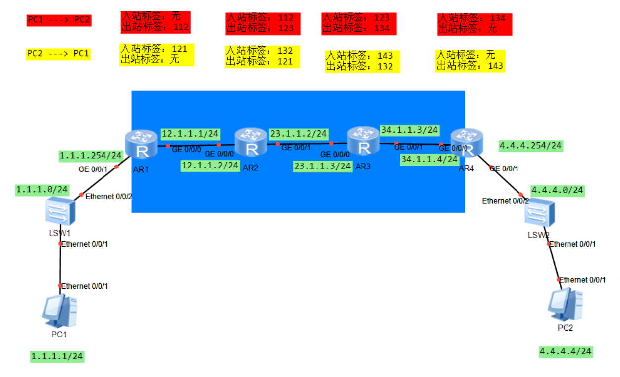
在进入MPLS相关配置之前要先按照拓扑图中的信息配置好设备IP。第一步:部署路由
1.在R1上配置到达4.4.4.0/24的静态路由,下一跳为 R2;
2.在R4上配置到达1.1.1.0/24的静态路由,下一跳为 R3;
3.R2和R3上根据标签进行转发,无需配置路由。


第二步:在设备上激活MPLS


第三步:配置静态LSP
PC1 —> PC2:
R1配置:
static-lsp ingress 1to4 destination 4.4.4.0 24 nexthop 12.1.1.2 out-label 112- 1

- static-lsp:设置静态的lsp
- ingress:当前LSR为LSP的入站LSR
- 1to4:当前LSP名字,自定义
- destination:指定目标网段,即定义FEC
- nexthop:指定下一跳IP地址,注意这个地址必须和路由表中到达destination的下一跳一致。
- out-label:指定出标签,注意图中配置的出标签为112(换行了)
R2配置:
static-lsp transit 1to4 incoming-interface g0/0/0 in-label 112 nexthop 23.1.1.3 out-label 123- 1

- transit:指定该LSR为中转LSR
- incoming-interface:指定入站的接口
- in-label:指定入站的标签
- nexthop:指定下一跳IP地址
- out-label:指定出站的标签
R3配置:
static-lsp transit 1to4 incoming-interface g0/0/0 in-label 123 nexthop 34.1.1.3 out-label 134- 1

R4配置:static-lsp egress 1to4 incoming-interface g0/0/0 in-label 134- 1

- egress:指定该LSR为LSP的出站LSP
注意三种类型的LSR的配置方式的区别。
PC2—>PC1
R4配置:
static-lsp ingress 4to1 destination 1.1.1.0 24 nexthop 34.1.1.3 out-label 143- 1
R3配置:
static-lsp transit 4to1 incoming-interface g0/0/1 in-label 143 nexthop 23.1.1.2 out-label 132- 1
R2配置:
static-lsp transit 4to1 incoming-interface g0/0/1 in-label 132 nexthop 12.1.1.1 out-label 121- 1
R1配置:
static-lsp egress 4to1 incoming-interface g0/0/0 in-label 121- 1
第四步:查看建立的LSP及验证
在LSR上执行下面的命令查看LSP:
display mpls lsp- 1


验证:在PC1上ping PC2,如果能ping通,则配置成功。 -
相关阅读:
scikit-learn 中 Boston Housing 数据集问题解决方案
Kubernetes学习篇之对象管理
【炼金术士】BatchSize对网络训练的影响
[附源码]java毕业设计学习教学辅助软件平台
FreeRTOS学习笔记(一)
对副业的选择无论是自媒体还是 Python接单 ,始终绕不开IT行业。
2023年03月 Python(一级)真题解析#中国电子学会#全国青少年软件编程等级考试
【c++】向webrtc学习容器操作
毕业设计-基于机器视觉的银行卡号识别系统
【理论】车辆双轴振动模型(一)
- 原文地址:https://blog.csdn.net/qq_70244454/article/details/133497466