-
自己设计CPU学习之路——基于《Xilinx FPGA应用开发》
1. 一个32组位宽为32的寄存器堆
- 框图

-
代码
- regfile.h
`ifndef __FEGFILE_HEADER__ `define __REGFILE_HEADER__ `define HIGH 1'b1 `define LOW 1'b0 `define ENABLE_ 1'b0 `define DISABLE_ 1'b1 `define DATA_W 32 `define DataBus 31:0 `define DATA_D 32 `define ADDR_W 5 `define AddrBus 4:0 `endif- 1
- 2
- 3
- 4
- 5
- 6
- 7
- 8
- 9
- 10
- 11
- 12
- 13
- 14
- 15
- 16
- 17
- regfile.v
`include "regfile2.h" module regfile2 ( input wire clk, input wire reset_, input wire [`AddrBus] addr, input wire [`DataBus] d_in, input wire we_, output wire [`DataBus] d_out ); reg [`DataBus] ff [`DATA_D-1:0]; //寄存器序列 integer i; assign d_out = ff[addr]; always @(posedge clk or negedge reset_) begin if (reset_ == `ENABLE_) begin for (i = 0;i < `DATA_D;i = i + 1) begin ff[i] <= #1{`DATA_W{1'b0}}; end end else begin if (we_ == `ENABLE_) begin ff[addr] <= #1 d_in; end end end endmodule- 1
- 2
- 3
- 4
- 5
- 6
- 7
- 8
- 9
- 10
- 11
- 12
- 13
- 14
- 15
- 16
- 17
- 18
- 19
- 20
- 21
- 22
- 23
- 24
- 25
- 26
- 27
- 28
- 29
- 30
2. ALU
module alu( input [2:0] a,b, input [1:0] sel, output reg [3:0] out ) always @(a,b,sel) begin case(sel) 2'b00: out = a+b; 2'b01: out = ~(a+b); 2'b10: out = a<<1; 2'b11: out = ~a; default:out = 4'b0000; endcase end endmodule- 1
- 2
- 3
- 4
- 5
- 6
- 7
- 8
- 9
- 10
- 11
- 12
- 13
- 14
- 15
3. 同步使能,异步复位的D触发器
module Dff ( input clk, input clr, input en, input D, output reg q, output qb ); assign qb = ~q; always @(posedge clk or posedge clr) begin if (clr) q <= 0;//异步复位 else if (en) q <= D;//同步使能 end endmodule- 1
- 2
- 3
- 4
- 5
- 6
- 7
- 8
- 9
- 10
- 11
- 12
- 13
- 14
这个Verilog模块实现了一个带有异步复位功能的D触发器。在这个模块中,异步复位由输入信号
clr控制。异步复位的实现方式是,当
clr信号为高电平(假定高电平表示复位时),触发器的输出q将被强制置为逻辑0,无论时钟信号clk和使能信号en的状态如何。这意味着,无论何时clr信号变为高电平,都会立即将q复位为0。以下是对代码的解释:
-
assign qb = ~q;行将qb定义为q的反相信号,即qb始终是q的逻辑反值。 -
always @(posedge clk or posedge clr) begin声明一个始终块,该块在时钟上升沿(posedge clk)或异步复位上升沿(posedge clr)时触发。 -
if (clr) q <= 0;行检查clr信号的状态。如果clr为高电平(即异步复位条件触发),则q被赋值为0,实现了异步复位。 -
else if (en) q <= D;行在没有异步复位的情况下,检查使能信号en。如果en为高电平,那么q将被赋值为输入信号D,实现了同步使能。
这个模块的功能是,当
clr信号为高电平时,无论何时都会将q置为0,而当clr信号为低电平且en信号为高电平时,q会根据输入信号D的值来更新。这使得在需要时可以通过异步复位来立即清除触发器的状态。4. 移位寄存器
module shift_reg ( input clk, input rst, input data_in, output reg [7:0] q ); always @(posedge clk) begin if (rst) q <= 0; else begin q[7:1] <= q[6:0]; q[0] <= data_in; end end endmodule- 1
- 2
- 3
- 4
- 5
- 6
- 7
- 8
- 9
- 10
- 11
- 12
- 13
- 14
- 15
- 16
5. 使用6个D触发器实现一个6位的寄存器
module DFlipFlop ( input clk, input clr_n, // 异步复位信号,低电平有效 input D, output reg Q ); always @(posedge clk or negedge clr_n) begin if (!clr_n) Q <= 1'b0; // 异步复位时,输出清零 else Q <= D; // 非复位时,将输入数据加载到输出 end endmodule module SixBitRegister ( input clk, input clr_n, input [5:0] data_input, output [5:0] data_output ); reg [5:0] q; // 6位寄存器的输出 integer i; always @(posedge clk or negedge clr_n) begin if (!clr_n) q <= 6'b0; // 异步复位时,全部位清零 else for (i = 0; i < 6; i = i + 1) DFlipFlop dff ( .clk(clk), .clr_n(clr_n), .D(data_input[i]), .Q(q[i]) ); // 使用循环实例化六个D触发器 end assign data_output = q; endmodule- 1
- 2
- 3
- 4
- 5
- 6
- 7
- 8
- 9
- 10
- 11
- 12
- 13
- 14
- 15
- 16
- 17
- 18
- 19
- 20
- 21
- 22
- 23
- 24
- 25
- 26
- 27
- 28
- 29
- 30
- 31
- 32
- 33
- 34
- 35
- 36
- 37
- 38
- 39
- 40
- 41
- 42
- 43
6. 按键产生时钟脉冲,移位寄存器
module shift_reg ( input btn, // 按键输入,用于产生时钟脉冲 output reg clk_pulse, // 时钟脉冲信号 input rst, input data_in, output reg [7:0] q ); reg clk_edge = 0; always @(posedge btn) begin clk_edge <= ~clk_edge; // 按键按下时切换时钟边沿 end always @(posedge clk_edge or posedge rst) begin if (rst) q <= 8'b0; else begin q[7:1] <= q[6:0]; q[0] <= data_in; end end // 产生时钟脉冲 always @(posedge clk_edge) begin clk_pulse <= 1'b1; end endmodule- 1
- 2
- 3
- 4
- 5
- 6
- 7
- 8
- 9
- 10
- 11
- 12
- 13
- 14
- 15
- 16
- 17
- 18
- 19
- 20
- 21
- 22
- 23
- 24
- 25
- 26
- 27
- 28
- 29
- 30
7. 串入并出74SL64芯片
module ShiftRegister_74LS164 ( input clk, // 时钟输入 input srclr, // 异步复位输入 input serial_in, // 串行输入 output [7:0] parallel_out // 并行输出 ); reg [7:0] shift_register; // 移位寄存器存储器件 always @(posedge clk or posedge srclr) begin if (srclr) shift_register <= 8'b0; // 异步复位时,寄存器清零 else shift_register <= {shift_register[6:0], serial_in}; // 数据移位 end assign parallel_out = shift_register; // 并行输出与寄存器值关联 endmodule- 1
- 2
- 3
- 4
- 5
- 6
- 7
- 8
- 9
- 10
- 11
- 12
- 13
- 14
- 15
- 16
- 17
- 18
- 19
8.同步使能、异步清零的16进制计数器

module counter_16( input clk, input clr, input en, output reg [3:0] q ); always @(posedge clk or posedge clr) begin if (q <= 0) q <= 0; else if (en) q <= q + 1; end endmodule- 1
- 2
- 3
- 4
- 5
- 6
- 7
- 8
- 9
- 10
- 11
- 12
//激励关键代码 initial fork ckl = 0; clr = 0; en = 0; forever begin #10 clk = ~clk; #25 clr = 1; #55 clr = 0; #35 en = 1; end join- 1
- 2
- 3
- 4
- 5
- 6
- 7
- 8
- 9
- 10
- 11
- 12
上面的Verilog代码片段展示了一个
initial块内的fork-join结构,该结构用于并发地控制信号clk、clr和en的变化。以下是对这段代码的详细解释:-
fork和join:fork和join是一对用于创建并发代码块的关键字。fork标志着代码分支的开始,允许同时执行多个线程。join表示所有分支线程都执行完毕后再继续执行后续的代码。在这个例子中,fork启动了一个并发线程,而join用于结束这个线程。 -
initial块:initial块是Verilog中用于模拟和初始化的代码块。在仿真开始时执行其中的代码。 -
初始化信号:在
initial块的开头,clk、clr、和en这三个信号都被初始化。它们的初始值分别是 0。 -
forever循环:forever关键字用于创建一个无限循环,表示其中的代码将一直执行下去。 -
#10、#25、#55、#35:这些是时间延迟操作符,用于指定等待的时间。#10表示等待 10 个时间单位,#25表示等待 25 个时间单位,以此类推。 -
时钟信号
clk的翻转:#10 clk = ~clk;表示在等待 10 个时间单位后,翻转时钟信号clk的状态,从 0 到 1 或从 1 到 0。这模拟了时钟的周期性振荡。 -
异步复位信号
clr的设置和清除:#25 clr = 1;表示在等待 25 个时间单位后,将异步复位信号clr设置为 1,表示触发异步复位。然后#55 clr = 0;表示在等待 55 个时间单位后,将clr再次设置为 0,表示清除异步复位。 -
使能信号
en的设置和清除:#35 en = 1;表示在等待 35 个时间单位后,将使能信号en设置为 1,表示启用某些操作。请注意,en之后没有清除,因此在整个仿真期间都会保持为 1。
9. 偶数分频
采用加法计数的方法,知识要对时钟的上升沿进行计数,因为输出波形的改变仅仅发生在时钟上升沿。
module divf_even ( input clk, output reg clk_N ); parameter N = 6; integer p; always @(posedge clk) begin if (p == N/2-1) begin p = 0; clk_N = ~clk_N; end else p = p + 1; end endmodule- 1
- 2
- 3
- 4
- 5
- 6
- 7
- 8
- 9
- 10
- 11
- 12
- 13
- 14
10. 奇数分频
奇数分频——错位异或法。对于实现占空比为50%的N倍奇数分频,首先进行上升沿出发的模N计数计数到一选定值时进行输出时钟翻转,得到一个占空比为50%的N分频时钟clk1;然后在下降沿,经过与上面选定时刻相差(N-1)/2时刻,反转另一个时钟,这样得到另一个占空比为50%的N分频时钟clk2.将clk1和clk2两个时钟进行异或运算,就得到了占空比为50%的奇数分频时钟。利用了相位差

module divf_oddn( input clk, output clk_N ); parameter N = 3; integer p = 0; reg clk_p = 0,clk_q = 0; always @(posedge clk) begin if (p == N-1) p <= 0; else p <= p + 1; end always @(posedge clk) begin if (p == N - 1) clk_p <= ~clk_p; end always @(negedge clk) begin if (p == (N-1)/2) clk_q <= ~clk_q; end assign clk_N = clk_p ^ clk_q; endmodule- 1
- 2
- 3
- 4
- 5
- 6
- 7
- 8
- 9
- 10
- 11
- 12
- 13
- 14
- 15
- 16
- 17
- 18
- 19
11. 2 n 2^n 2n 分频
module divf_2pown ( input clk, input rst, output clk2, output clk4, output clk8, output clk16 ); reg [3:0] count; always @(posedge clk) begin if (rst) begin count <= 0; end else begin count <= count + 1; end end assign clk2 = count[0]; assign clk4 = count[1]; assign clk8 = count[2]; assign clk16 = count[3]; endmodule- 1
- 2
- 3
- 4
- 5
- 6
- 7
- 8
- 9
- 10
- 11
- 12
- 13
- 14
- 15
- 16
- 17
- 18
- 19
- 20
- 21
- 22
12. 秒计数器
- 1s实现加1计数,计到59后再从零计数
- 同步清零,用拨码开关控制同步清零,led灯显示

top 模块
module second_top ( clk,bmkg0,led ); input clk; input bmkg0; output [7:0] led; wire [7:0] sec; wire clk_1HZ; second_divf U1(.clk_50MHZ(clk), .clk_1HZ(clk_1HZ)); second U2(.clk_1HZ(clk_1HZ), .clr(bmkg0), sec(sec)); second_disp U3(.sec(sec), .q(led)); endmodule- 1
- 2
- 3
- 4
- 5
- 6
- 7
- 8
- 9
- 10
- 11
- 12
- 13
- 14
- 15
- 16
分频模块 50MHz–> 1Hz
module second_divf ( clk_50MHZ,clk_1HZ ); input clk_50MHZ; output reg clk_1HZ; reg [25:0] cnt; always @(posedge clk_50MHZ) begin if (cnt == 25000000-1) begin clk_1HZ = ~clk_1HZ; cnt <= 0; end else begin cnt = cnt + 1; end end endmodule- 1
- 2
- 3
- 4
- 5
- 6
- 7
- 8
- 9
- 10
- 11
- 12
- 13
- 14
- 15
计数模块
module second( clk_1HZ,clr,sec ); input clk_1HZ; input clr; output reg [7:0] sec; always @(posedge clk_1HZ or posedge clr) begin if (clr) begin sec <= 0; end else if (sec == 59) sec <= 0; else sec <= sec + 1; end endmodule- 1
- 2
- 3
- 4
- 5
- 6
- 7
- 8
- 9
- 10
- 11
- 12
- 13
显示模块
module second_disp ( sec,q ); input [7:0] sec; output [7:0] q; assign q = sec; endmodule- 1
- 2
- 3
- 4
- 5
- 6
- 7
13. 序列检测器
再连续信号中,检测是否包含“110”序列,当包含该序列时,指示灯就亮,否则指示灯灭。
顶层模块
module SerialTect_top ( clk,key,led ); input clk; input [1:0] key; output led; wire pulse; wire [1:0] key_debounce; IP_smg_divf U1(.clk_50MHz(clk), .clk_190Hz(clk_190Hz)); IP_key_debounce U2(.key_debounce(key_debounce[0]), .clk_190Hz(clk_190Hz), .key0(key[1])); IP_pulse_gen U4(.clk(clk), .key(|key_bounce), .pulse(pulse)); Serial_compare U5(.clk(pulse), .serialData(key_debounce[1]), .result(led)); endmodule- 1
- 2
- 3
- 4
- 5
- 6
- 7
- 8
- 9
- 10
- 11
- 12
- 13
- 14
- 15
- 16
- 17
- 18
- 19
- 20
- 21
分频模块
按键消抖模块
脉冲信号模块
序列检测模块
module Serial_compare ( clk,serialData,result ); input clk; input serialData; output result; parameter s0 = 2'b00,s1 = 2'b01,s2 = 2'b10,s3 = 2'b11; reg [1:0] next_st = s0; always @(posedge clk) begin case (next_st) s0: if (serialData == 1'b1) next_st = s1; else next_st = s0; s1: if (serialData == 1'b1) next_st = s2; else next_st = s0; s2: if (serialData == 1'b1) next_st = s2; else next_st = s3; s3: if (serialData == 1'b1) next_st = s1; else next_st = s0; default: next_st = s0; endcase end assign result = (next_st == s3)?1:0; endmodule- 1
- 2
- 3
- 4
- 5
- 6
- 7
- 8
- 9
- 10
- 11
- 12
- 13
- 14
- 15
- 16
- 17
- 18
- 19
- 20
- 21
- 22
- 23
- 24
- 25
14. 简易处理器设计
1. 设计要求
- 完成处理器指令集的设计
- 完成处理器的设计,要求能够识别处理指令集中的任何指令
- 设计一段程序,要求该段程序用到指令集中的所有指令,并通过处理器运行这段程序得到结果
2. 设计
- 处理器的组成结构

- 简易处理器的功能
完成 2*(0+1+2+…+10)=?
- 指令系统的设计

- 寄存器传输指令
- 装在指令
- 算术运算指令:完成加减运算
- 逻辑移位指令:完成左移操作
- 存储指令
- 分支指令
所有的指令都包含4位操作码和12位操作数
汇编语言描述

机器码描述

3. 设计实现
3.1 顶层设计

- CPU顶层测试模块
module cpu_mem_test ( clk,rst,key,duan,wei ); input clk,rst; input [1:0] key; output [7:0] duan; output [3:0] wei; wire [39:0] rf_data; wire start; wire [7:0] PC; wire [15:0] IR; cpu_mem cpu_mem( .clk(clk), .rst(rst), .start(start), .rf_data(rf_data), .PC(PC), .IR(IF) ); fpag_step_ctrl step_ctrl( .clk(clk), .rst(rst), .key(key), .start(start), .duan(duan), .wei(wei), .PC(PC), .IR(IR), .rf_data(rf_data) ) ; endmodule- 1
- 2
- 3
- 4
- 5
- 6
- 7
- 8
- 9
- 10
- 11
- 12
- 13
- 14
- 15
- 16
- 17
- 18
- 19
- 20
- 21
- 22
- 23
- 24
- 25
- 26
- 27
- 28
- 29
- 30
- 31
- 32
- 含ROM和RAM的CPU设计
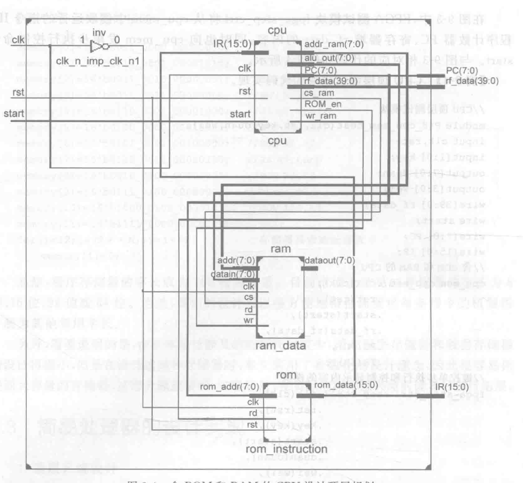
module cpu_mem ( clk,rst,start,rf_data,PC,IR ); input clk,rst; input start; output [39:0] rf_data; output [7:0] PC; output [15:0] IR; wire ROM_en; wire [15:0] IR; wire wr_ram,cs_ram; wire [7:0] addr_ram; wire [7:0] alu_out; wire clk_n; assign clk_n = ~clk; cpu cpu( .clk(clk), .rst(rst), .start(start), .ROM_en(ROM_en), .IR(IR), .PC(PC), .rf_data(rf_data), .wr_ram(wr_ram), .cs_ram(cs_ram), .addr_ram(addr_ram), .alu_out(alu_out) ); rom rom_instruction( .clk(clk_n), .rst(rst), .rd(ROM_en), .rom_data(IR), .rom_addr(PC) ); ram ram_data( .clk(clk_n), .wr(wr_ram), .cs(cs_ram), .addr(addr_ram), .datain(alu_out) ); endmodule- 1
- 2
- 3
- 4
- 5
- 6
- 7
- 8
- 9
- 10
- 11
- 12
- 13
- 14
- 15
- 16
- 17
- 18
- 19
- 20
- 21
- 22
- 23
- 24
- 25
- 26
- 27
- 28
- 29
- 30
- 31
- 32
- 33
- 34
- 35
- 36
- 37
- 38
- 39
- 40
- 41
- 42
- 43
- 44
- 将CPU进一步规划成datapath和controller
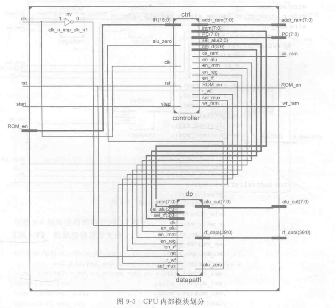
- cpu 内部模块划分——包括数据路径和控制器
module cpu ( clk,rst,start,ROM_en,IR, PC,rf_data,wr_ram,cs_ram,addr_ram, alu_out ); input clk,rst; input start; input [15:0] IR; output [7:0] PC; output ROM_en; output wr_ram,cs_ram; output [7:0] addr_ram; output [7:0] alu_oout; output [39:0] rf_data; wire [7:0] imm; wire [3:0] sel_rf; wire [2:0] sel_alu; wire sel_mux; wire r_wf,en_rf,en_reg,en_alu,en_imm,alu_zero; wire clk_n; assign clk_n = ~clk; dp datapath( .rst(rst), .clk(clk_n), .r_wf(r_wf), .en_rf(en_rf), .en_reg(en_reg), .en_alu(en_alu), .en_imm(en_imm), .sel_rf(sel_rf), .sel_alu(sel_alu), .sel_mux(sel_mux), .imm(imm), .alu_zero(alu_zero), .alu_out(alu_out), .rf_data(rf_data) ); ctrl controller( .rst(rst), .start(start), .clk(clk), .alu_zero(alu_zero), .r_wf(r_wf), .en_rf(en_rf), .en_reg(en_reg), .en_alu(en_alu), .en_imm(en_imm), .sel_rf(sel_rf), .sel_alu(sel_alu), .sel_mux(sel_mux), .imm(imm), .PC(PC), .IR(IR), .ROM_en(ROM_en), .wr_ram(wr_ram), .cs_ram(cs_ram), .addr_ram(addr_ram) ); endmodule- 1
- 2
- 3
- 4
- 5
- 6
- 7
- 8
- 9
- 10
- 11
- 12
- 13
- 14
- 15
- 16
- 17
- 18
- 19
- 20
- 21
- 22
- 23
- 24
- 25
- 26
- 27
- 28
- 29
- 30
- 31
- 32
- 33
- 34
- 35
- 36
- 37
- 38
- 39
- 40
- 41
- 42
- 43
- 44
- 45
- 46
- 47
- 48
- 49
- 50
- 51
- 52
- 53
- 54
- 55
- 56
- 57
- 58
- 59
- 数据路径部分细分框图

- 数据路径顶层文件
module dp( rst,clk,r_wf,en_rf,en_reg,en_alu,en_imm,sel_rf, sel_alu,sel_mux,imm,alu_zero,alu_out,rf_data ); input rst,clk,r_wf,en_rf,en_reg,en_alu,en_imm; input [7:0] imm; input [2:0] sel_alu; input [3:0] sel_rf; input sel_mux; output alu_zero; output [39:0] rf_data; output [7:0] alu_out; wire [7:0] op1,op2,out_imm,out_rf; register register0( .clk(clk), .en(en_reg), .in(op1), .out(op2) ) ; register register1( .clk(clk), .en(en_imm), .in(imm), .out(out_imm) ); mux21 mux0( .sel(sel_mux), .in1(out_imm), .in2(out_rf), .out(op1) ); alu alu0( .clk(clk), .en(en_alu), .sel(sel_alu), .in1(op1), .in2(op2), .out(alu_out), .alu_zero(alu_zero) ); rf rf0( .rst(rst), .clk(clk), .r_w(r_wf), .enb(en_rf), .in(alu_out), .sel(sel_rf), .out(out_rf), .rf_data(rf_data) ); endmodule- 1
- 2
- 3
- 4
- 5
- 6
- 7
- 8
- 9
- 10
- 11
- 12
- 13
- 14
- 15
- 16
- 17
- 18
- 19
- 20
- 21
- 22
- 23
- 24
- 25
- 26
- 27
- 28
- 29
- 30
- 31
- 32
- 33
- 34
- 35
- 36
- 37
- 38
- 39
- 40
- 41
- 42
- 43
- 44
- 45
- 46
- 47
- 48
- 49
- 50
- 51
3.2 基本部件设计
- ALU
module alu ( clk,en,sel,in1,in2,out,alu_zero; ); input en,clk; input [2:0] sel; input [7:0] in1,in2; output reg[7:0]out; output reg alu_zero; always @(posedge clk) begin if (en) case(sel) 3'b000: out = in1; 3'b001: if (in1 == 0) alu_zero = 1;else alu_zero = 0; 3'b010: out = in1 + in2; 3'b011: out = in1 - in2; 3'b100: out = in1<- 1
- 2
- 3
- 4
- 5
- 6
- 7
- 8
- 9
- 10
- 11
- 12
- 13
- 14
- 15
- 16
- 17
- 18
- 19
- 20
- 21

- 异步使能寄存器

module register ( clk,en,in,out ); input clk,en; input [7:0] in; output reg[7:0] out; reg [7:0] val; always @(posedge clk) val <= in; always @(en,val) begin if (en == 1'b1) out <= val; else ; end endmodule- 1
- 2
- 3
- 4
- 5
- 6
- 7
- 8
- 9
- 10
- 11
- 12
- 13
- 14
- 通用寄存器
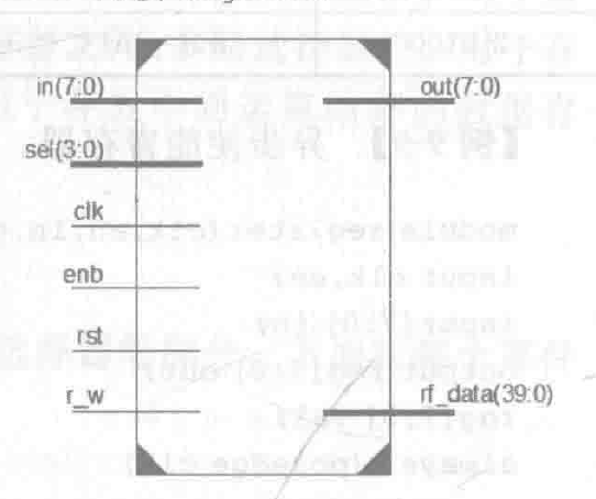
module rf ( rst,clk,r_w,enb,in,sel,out,rf_data ); input rst,clk,enb,r_w; input [7:0] in; input [3:0] sel; output reg[7:0]out; output [39:0] rf_data; reg [7:0] reg_file[0:15]; integer i; assign rf_data = {reg_file[4],reg_file[3], reg_file[2],reg_file[1],reg_file[0]}; always @(posedge rst or posedge clk) begin if (rst) begin for (i = 0;i < 15;i = i + 1) reg_file[i] <= 0; end else if (enb == 1) begin if (r_w == 0) reg_file[sel] <= in; else out <= reg_file[sel]; end end endmodule- 1
- 2
- 3
- 4
- 5
- 6
- 7
- 8
- 9
- 10
- 11
- 12
- 13
- 14
- 15
- 16
- 17
- 18
- 19
- 20
- 21
- 22
- 二选一多路选择器

module mux21 ( sel,in1,in2,out ); input sel; input [7:0] in1,in2; output[7:0] out; assign out = (sel)?in2:in1; endmodule- 1
- 2
- 3
- 4
- 5
- 6
- 7
- 8
- 控制器
控制器提供必要的控制信号,使得数据流通过数据路径后达到预期的功能。控制器部分使用状态机计数来实现,这个状态机根据当前的状态和输入的信号值,输出更新后的状态和相应的控制信号。
module ctrl ( rst,start,clk,alu_zero,r_wf,en_rf,en_reg,en_alu,en_imm, sel_rf,sel_alu,sel_mux,imm,PC,IF,ROM_en,wr_ram, cs_ram,addr_ram ); input rst,start,clk; input alu_zero; input [15:0] IR; output reg r_wf,en_rf,en_reg,en_alu,en_imm; output reg[3:0]sel_rf; output reg[2:0]sel_alu; output reg sel_mux; output reg[7:0]imm,PC; output reg ROM_en; output reg wr_ram,cs_ram; output reg[7:0]addr_ram; parameter s0 = 6'b000000,s1 = 6'b000001,s2 = 6'b000010, s3 = 6'b000011,s4 = 6'b000100,s5 = 6'b000101,s5_2 = 6'b000110,s5_3 = 6'b000111, s6 = 6'b001000,s6_2 = 6'b001001,s6_3 = 6'b001010, s6_4 = 6'b001000,s6_5 = 6'b001100, s7 = 6'b001101,s7_2 = 6'b001110,s7_3 = 6'b001111, s7_4 = 6'b010000,s7_5 = 6'b010001, s8 = 6'b010010,s8_2 = 6'b010011,s8_3 = 6'b010100, s9 = 6'b010101,s9_2 = 6'b010110,s9_3 = 6'b010111, s10 = 6'b100000,s10_2 = 6'b100001,s10_3 = 6'b100010, s11 = 6'b100011,s11_2 = 6'b100100,s11_3 = 6'b100101, s11_4 = 6'b100110,s11_5 = 6'b100111, s12 = 6'b101000,done = 6'b101001; reg [5:0] state; parameter loadi = 4'b0011,add = 4'b0100,sub = 4'b0101, jz = 4'b0110,store = 4'b1000,shiftL = 4'b0111,reg2reg = 4'b0010, halt = 4'b1111; reg [3:0] OPCODE; reg [7:0] address; reg [3:0] register; always @(posedge rst or posedge clk) begin sel_mux <= 1'b1; en_rf <= 1'b0; en_reg <= 1'b0; en_alu <= 1'b0; en_imm <= 1'b0; ROM_en <= 1'b0; wr_ram <= 1'b0; cs_ram <= 1'b0; addr_ram <= 0; if (rst) begin state <= s0; PC <= 0; end else begin case (state) s0: begin PC <= 0; state <= s1; end s1: begin if (start == 1'b1) begin ROM_en <= 1; state <= s2; end else state <= s1; end s2: begin OPCODE <= IR[15:12]; register <= IR[11:8]; address <= IR[7:0]; state <= s3; end s3: begin PC <= PC + 8'b1; state <= s4; end s4: begin case (OPCODE) loadi: state <= s5; add: state <= s6; sub: state <= s7; jz: state <= s8; store: state <= s9; reg2reg:state <= s10; shiftL: state <= s11; halt: state <= done; default:state <= s1; endcase end s5: begin imm <= address; en_imm <= 1; state <= s5_2; end s5_2:begin sel_mux <= 0; en_alu <= 1; sel_alu <= 3'b000; state <= s5_3; end s5_3:begin en_rf <= 1; r_wf <= 0; sel_rf <= register; state <= s12; end s6:begin sel_rf <= IR[7:4]; en_rf <= 1; r_wf <= 1; state <= s6_2; end s6_2:begin en_reg <= 1; state <= s6_3; end s6_3:begin sel_rf <= register; en_rf <= 1; r_wf <= 1; state <= s6_4; end s6_4:begin en_alu <= 1; sel_alu <= 3'b010; state <= s6_5; end s6_5:begin sel_rf <= register; en_rf <= 1; r_wf <= 0; state <= s12; end s7: begin sel_rf <= IF[7:4]; en_rf <=1; r_wf <= 1; state <= s7_2; end s7_2: begin en_reg <= 1; state <= s7_3; end s7_3: begin sel_rf <= register; en_rf <= 1; r_wf <= 1; state <= s7_4; end s7_5: begin sel_rf <= register; en_rf <= 1; r_wf <= 0; state <= s12; end s8: begin en_rf <= 1; r_wf <= 1; sel_rf <= register; state <= s8_2; end s8_2: begin en_rf <= 1; sel_alu <= 3'b001; state <= s8_3; end s8_3: begin if (alu_zero == 1) PC <= address; state <= s12; end s9: begin sel_rf <= register; en_rf <= 1; r_wf <= 1; state <= s9_2; end s9_2: begin en_alu <= 1; sel_alu <= 3'b000; state <= s9_3; end s9_3: begin cs_ram <= 1; wr_ram <= 1; addr_ram <= address; state <= s12; end s10: begin sel_rf <= IR[7:4]; en_rf <= 1; r_wf <= 1; state <= s10_2; end s10_2: begin en_alu <= 1; sel_alu <= 3'b000; state <= s10_3; end s10_3:begin sel_rf <= register; en_rf <= 1; r_wf <= 0; state <= s12; end s11: begin imm <= address; en_imm <= 1; state <= s11_2; end s11_2: begin sel_mux <= 0; en_reg <= 1; state <= s11_3; end s11_3: begin sel_rf <= register; en_rf <= 1; r_wf <= 1; state <= s11_4; end s11_4: begin en_alu <= 1; sel_alu <= 3'b100; state <= s11_5; end s11_5: begin sel_rf <= register; en_rf <= 1; r_wf <= 0; state <= s12; end s12: state <= s1; done: state <= done; default:; endcase end end endmodule- 1
- 2
- 3
- 4
- 5
- 6
- 7
- 8
- 9
- 10
- 11
- 12
- 13
- 14
- 15
- 16
- 17
- 18
- 19
- 20
- 21
- 22
- 23
- 24
- 25
- 26
- 27
- 28
- 29
- 30
- 31
- 32
- 33
- 34
- 35
- 36
- 37
- 38
- 39
- 40
- 41
- 42
- 43
- 44
- 45
- 46
- 47
- 48
- 49
- 50
- 51
- 52
- 53
- 54
- 55
- 56
- 57
- 58
- 59
- 60
- 61
- 62
- 63
- 64
- 65
- 66
- 67
- 68
- 69
- 70
- 71
- 72
- 73
- 74
- 75
- 76
- 77
- 78
- 79
- 80
- 81
- 82
- 83
- 84
- 85
- 86
- 87
- 88
- 89
- 90
- 91
- 92
- 93
- 94
- 95
- 96
- 97
- 98
- 99
- 100
- 101
- 102
- 103
- 104
- 105
- 106
- 107
- 108
- 109
- 110
- 111
- 112
- 113
- 114
- 115
- 116
- 117
- 118
- 119
- 120
- 121
- 122
- 123
- 124
- 125
- 126
- 127
- 128
- 129
- 130
- 131
- 132
- 133
- 134
- 135
- 136
- 137
- 138
- 139
- 140
- 141
- 142
- 143
- 144
- 145
- 146
- 147
- 148
- 149
- 150
- 151
- 152
- 153
- 154
- 155
- 156
- 157
- 158
- 159
- 160
- 161
- 162
- 163
- 164
- 165
- 166
- 167
- 168
- 169
- 170
- 171
- 172
- 173
- 174
- 175
- 176
- 177
- 178
- 179
- 180
- 181
- 182
- 183
- 184
- 185
- 186
- 187
- 188
- 189
- 190
- 191
- 192
- 193
- 194
- 195
- 196
- 197
- 198
- 199
- 200
- 201
- 202
- 203
- 204
- 205
- 206
- 207
- 208
- 209
- 210
- 211
- 212
- 213
- 214
- 215
- 216
- 217
- 218
- 219
- 220
- 221
- 222
- 223
- 224
- 225
- 226
- 227
- 228
- 229
- 230
- 231
- 232
- 233
- 234


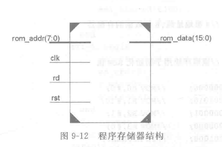
- 程序存储器
module rom ( clk,rst,rd,rom_data,rom_addr ); parameter M = 16,N = 8; input clk,rst,rd; input [N-1:0] rom_addr; output reg[M-1:0] rom_data; reg [M-1:0] memory[0:2**N-1]; always @(posedge clk or posedge rst) begin if (rst) begin:init integer i; memory[0]=16'b0011_0000 00000000; //MOV RO,#0; memory[1]=16'b0011_0001 00001010; //MOV R1,#10; memory[2]=16'b0011_0010_00000001; //MOV R2,#1; memory[3]=16'b0011 0011 00000000; //MOV R3,#0; memory[4]=16'b0110_0001 00001000; //JZ R1,NEXT; memory[5]=16'b0100_0000_00010000; //ADD R0,R1; memory[6]=16'b0101 0001 00100000; //SUB R1,R2; memory[7]=16'b0110_0011 00000100; //JZ R3,Lo0p memory[8]=16'b0010_0100_00000000; //MOV R4,R0 memory[9]=16'b0111_0100_00000001; //RLR4,#1 memory[10]=16'b1000_0100_00001010;//MOV 10H,R4memory[11J=16'b11110000 00001011; //halt for(i=12;i<(2**N);i=i+1) //存储器其余地址存放0 memory[i] = 0; end else begin:read if (rf) rom_data = memory[rom_addr]; end end endmodule- 1
- 2
- 3
- 4
- 5
- 6
- 7
- 8
- 9
- 10
- 11
- 12
- 13
- 14
- 15
- 16
- 17
- 18
- 19
- 20
- 21
- 22
- 23
- 24
- 25
- 26
- 27
- 28
- 29
- 30
- 31
- 32
- 33
- 34
- 35
- 36
- 37
- 38
- 39
- 40
- 41
- 数据存储器
module ram ( clk,rd,wf,cs,addr,datain,dataout ); parameter M = 8,N = 8; input rd,wr,cs,clk; input [N-1:0]addr; input [M-1:0]datain; output reg[M-1:0] dataout; reg [M-1:0] memory [0:2**N-1]; always @(posedge clk) begin:p0 if(cs) if (rd) dataout <= memory[addr]; else if (wr) memory[addr] <= datain; else dataout <= 'bz; end endmodule- 1
- 2
- 3
- 4
- 5
- 6
- 7
- 8
- 9
- 10
- 11
- 12
- 13
- 14
- 15
- 16
- 17

4. 上Vivado


跑出来了,不知道对不对

机房动环监控系统厂家品牌
【P37】JMeter 仅一次控制器(Once Only Controller)
查看docker容器中的ip
【zabbix Java开发教程】docker部署zabbix及api获取实战教程
dll文件反编译源代码 C#反编译 dotpeek反编译dll文件后export
Leetcode 第1342题:将数字变成 0 的操作次数 (位运算解题法详解)
spring复习(第二天上午)(黑马版)
shell编程
[Spring cloud alibaba][Sentinel][Gateway] 微服务整合sentinel流控未发现注册服务(监控空白问题)