-
NCO IP Core
NCO IP Core Features
• 32-bit precision for angle and magnitude
• Source interface compatible with the Avalon Interface Specification
• Multiple NCO architectures:
— Multiplier-based implementation using DSP blocks or logic elements (LEs),
(single cycle and multi-cycle)
— Parallel or serial CORDIC-based implementation
— ROM-based implementation using embedded array blocks (EABs), embedded
system blocks (ESBs), or external ROM
• Single or dual outputs (sine/cosine)
• Variable width frequency modulation input
• Variable width phase modulation input
• User-defined frequency resolution, angular precision, and magnitude precision
• Frequency hopping
• Multichannel capability
• Simulation files and architecture-specific testbenches for VHDL and Verilog HDL
• Dual-output oscillator and quaternary frequency shift keying (QFSK) modulator
example designsTypically, you can use NCOs in communication systems as quadrature carrier
generators in I-Q mixers, in which baseband data is modulated onto the orthogonal
carriers in one of a variety of ways.Simple Modulator

You can also use NCOs in all-digital phase-locked-loops (PLLs) for carrier
synchronization in communications receivers, or as standalone frequency shift keying
(FSK) or phase shift keying (PSK) modulators. In these applications, the phase or the
frequency of the output waveform varies directly according to an input data stream.
You can implement ROM-based, CORDIC-based, and multiplier-based NCO
architectures,. The wizard also includes time and frequency domain graphs that
dynamically display the functionality of the NCO, based on your parameter settings.
To decide which NCO implementation to use, consider the spectral purity, frequency
resolution, performance, throughput, and required device resources. Also, consider
the trade-offs between some or all of these parameters.
The NCO IP core allows you to generate a variety of NCO architectures. Your custom
NCO includes both time- and frequency-domain analysis tools. The custom NCO
outputs a sinusoidal waveform in two's complement representation.
The waveform for the generated sine wave is defined by the following equation: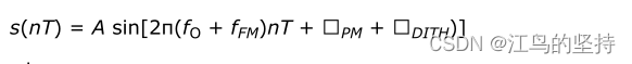
where:
• T is the operating clock period
• fO is the unmodulated output frequency based on the input value ϕINC
• fFM is a frequency modulating parameter based on the input value ϕFM
• ΦPM is derived from the phase modulation input value P and the number of bits
(Pwidth) used for this value by the equation: ϕPM = P/2^Pwidth
• ΦDITH is the internal dithering value
• A is 2N-1 where N is the magnitude precision (and N is an integer in the range 10
to 32
The generated output frequency, fo for a given phase increment, ϕinc is determined by
the equation: f0 = ϕinc fclk / 2M Hz
where M is the accumulator precision and fclk is the clock frequency
The minimum possible output frequency waveform is generated for the case where
ϕinc= 1. This case is also the smallest observable frequency at the output of the NCO,
also known as the frequency resolution of the NCO, fres given in Hz by the equation:
For example, if a 100 MHz clock drives an NCO with an accumulator precision of 32
bits, the frequency resolution of the oscillator is 0.0233 Hz. For an output frequency of
6.25 MHz from this oscillator, you should apply an input phase increment of:
The NCO MegaCore function automatically calculates this value, using the specified
parameters. IP Toolbench also sets the value of the phase increment in all testbenches
and vector source files it generates.
Similarly, the generated output frequency, fFM for a given frequency modulation
increment, ϕFM is determined by the equation:
where F is the modulator resolution
The angular precision of an NCO is the phase angle precision before the polar-to-
cartesian transformation. The magnitude precision is the precision to which the sine
and/or cosine of that phase angle can be represented. The effects of reduction or
augmentation of the angular, magnitude, accumulator precision on the synthesized
waveform vary across NCO architectures and for different fo/fclk ratios.
You can view these effects in the NCO time and frequency domain graphs as you
change the NCO IP core parameters. -
相关阅读:
特征选择技术总结
RabbitMQ核心笔记,带你深入理解消息中间件技术之RabbitMQ
接口项目实战
windows10通过coursier安装scala
提升珠宝管理效率的新零售行业RFID应用解决方案
24.Python文件I/O(二)【异常处理&断言assert】
[附源码]计算机毕业设计JAVAjsp高校学生资助信息系统
CentOS7 安装 mysql8
【重学C++】04 | 说透C++右值引用、移动语义、完美转发(上)
iOS App更换图标Logo(本地更换)
- 原文地址:https://blog.csdn.net/Calvin790704/article/details/128074854